SiRFatlasV
Hardware Design Guide
January, 2010
SiRF Design Guide
– Proprietary and Confidential
4
B
OOT
C
ONFIGURATION
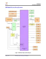
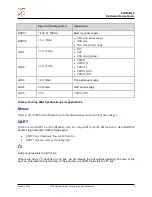
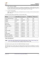
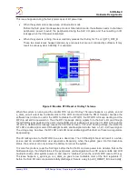
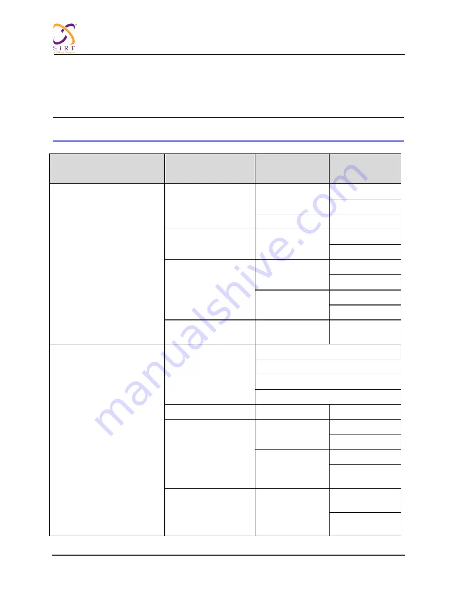
SiRFatlasV supports many types of boot media including NAND Flash and SD cards. The boot mode can
be set through the mode configuration pins according to the table below.
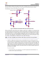
NOTE
–
Set the pins with pull-up or pull-down resistors (10 kOhm to 100 kOhm), do not leave these pins
set to float.
Working Mode
X_TEST_MODE[5:4]
Sub-Mode
X_TEST_MODE[3:2]
Feature 1
X_TEST_MODE[1]
Feature 0
X_TEST_MODE[0]
2'B00: Normal
2'B01: Normal With ARM JTAG
2'B10: Function ATE
2'B00: Embedded ROM
NAND Boot (SLC)
1'b0: SLC
1'b0: 2KB page
1'b1: 4KB page
1'b1: LBA-Nand
1'bx: 2KB page
2'B01: NAND Boot(SLC) 1'bx: Don't Care
1'b0: 512B page
1'b1: 2KB page
2'B10: Embedded ROM
NAND Boot (MLC)
1'b0: ECC 12bit per
1KB
1'b0: 2KB page
1'b1: 4KB page
1'b1: ECC 24bit per
1KB
1'b0: 4KB page
1'b1: 8KB page
2'B11: Embedded ROM
SD/MMC Boot
-
-
2'B11: TEST MODE
2'B00: Scan Mode
2’b00: INTEST_AC_DC
2’b01: EXTEST_AC_DC
2’b10: Reserved
2’b11: Reserved
2'B01: Reserved
-
-
2'B10: CHIP TEST1
1’b0: Boundary
Scan
1’b0: NANDTree
1’b1: BSD
1’b1: Macro Test0
1’b0: BIST
1’b1: Efuse
(x_reset_b = 1'b0)
2'B11: CHIP TEST2
1’b0: Macro Test1
1’b0: USB PHY
Stand Alone TEST
1’b1: TSC/PLL
TEST