SiRFatlasV
Hardware Design Guide
January, 2010
SiRF Design Guide
– Proprietary and Confidential
16
then the peripheral enable control signals will be reset to
“disabled” before the I/O and Core power are
discharged, then the I/O leakage dead-loop will be destroyed, and the system will become stable.
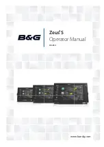
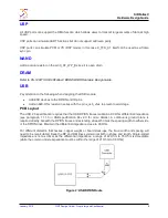
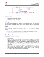
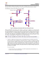
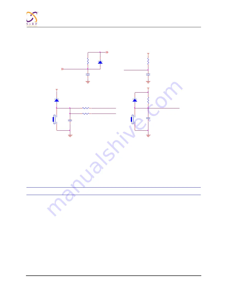
The following is a work around circuit to solve this problem.
Figure 10: Workaround for Random RTC Reset or On Key 15s Issue
When a random RTC reset or On key issue happens, x_system_en is pulled low, so x_reset_b will also
be pulled low quickly via the diode between x_reset_b and x_system_en. Before the Core and I/O power
are really discharged the SoC logic is reset and the I/Os which control the enabled peripherals will go to
the default reset status. The hardware design should guarantee these control signals are set to
“disable”
at the default reset stage, check the SiRFatlasV Datasheet pin list to find every I/O pad
’s reset status,
then based on the peripheral
’s enable/disable level, add external pull-up or pull-down resisters to make
sure all these enable signals are in
“disable” status at the default reset stage
NOTE
–
RC delay of X_RESET_B is about 20ms and RC delay of X_RTC_RST_B is about 880ms.
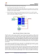
System is in deep-sleep or hibernation mode, with peripheral power on and drive signal to SoC
When the system goes into deep-sleep or hibernation mode, x_system_en is pulled low, and most
of the SoC
’s power is disabled. However there is still a chance that some external modules are
powered on and can drive the output signals high or toggle to the SoC pads. For example, the
debug module or external TMC or Radar module uses an external adaptor for power and has a
UART connection between the GPS device and the module. In these cases, there may be I/O
leakage from the powered module to the power-off SoC
’s I/O VDD. This leakage may result in
potential system instability.
To solve the problem:
–
Use the above work around method to ensure that the peripherals are disabled before the
SoC I/O and core power are discharged.
X_SY STEM_EN
Discharge if power off
D103
MA2S728
1
2
R139
51K 1%
C127
2.2uF
X_SY STEM_EN
C101
1uF/10V
X_RESET_B
X_RESET_B
X_RTC_RST_B
R140
510K 1%
1
2
VDDIO_RTC
R166
NC
C158
100nF
C159
100nF
D101
MA2S728
1
2
S101
1
2
VDDIO_RTC
Warm RESET
R160
10K
D102
MA2S728
1
2
X_ON_KEY _B
VDDIO_RTC
S102
1
2
X_RTC_RST_B
X_GPIO8
R165
0R
RTC RESET