background image

 DOC06501_Revision 


ATS-6501 Users Guide


37 

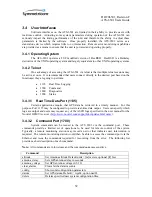
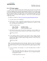
3.6.1 FTP Data Logging 


Data can be recorded and stored on the ATS-6501 and can be retrieved via a FTP client 

(username: ftp, password: ftp).  The logs that are stored are determined by the user and can be one 
of any of the ASCII logs specified in the Novatel OEMV user manual.  To set up data logging 
users will need to follow the steps outlined below to set up the type of data to be logged, log file 
intervals, maximum number of log files to store, set up the filename schema, set the file 
compression on or off, and then turn the logging on.  Users can also verify the data logging 
configuration settings. 
 

The OEMV user manual is at: (

http://www.novatel.com/support/docupdates.htm#oemv


A.


Access the system via the command port. 

 
B.


Use the 

log ftp <novalog> 

command to set up they data type to be sent over the data port.  

The 

novalog

 text on the command line specifies which data type to forward over this 

port.  Some examples are provided below. 


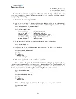
ATS-6501> log ftp timea ontime 1 
 

ionutca  onchanged 

// log IONO & UTC data 

rawalma onchanged 

// log almanac on startup 

rangea  ontime 60   

// L1/L2 observations @ 60 seconds 


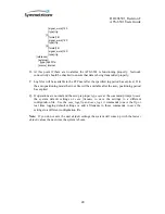
C.


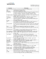
Set the interval for the log file to the desired value using the 

log_interval

 command.  Log 

interval value is in minutes and can be between 1 and 30 minutes.  Default is 15 minutes. 


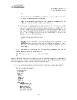
ATS-6501>log_interval 15 
OK 

 
D.


Set the maximum number of log files for the system to hold in memory using the 

log_number

 command.  If the logs in the storage directory exceed the maximum number 

of logs then the oldest log will be deleted to ensure that there is room for new logs.  
Default is 100 log files. 


ATS-6501>log_number 4 
OK 

 
Note:

  Your data retrieval setup will need to take these values into account.  The maximum 

time the logs will be available on the system is the log_interval * log_files, in the examples 
above that is 60 minutes.  If you are not retrieving the files frequently enough you will lose 
data. 
 
E.


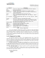
Use the 

log_filename (user|timestamp) 

to set up the file naming scheme.  Default is 

timestamp


a.


When using the 

user

 file naming scheme you will also need to provide the file 

prefix, the number of digits you would like to use as the unique file identifier, 
and the suffix for the file. 


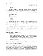
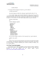
ATS-6501>log_filename user Test 4 dat 

Summary of Contents for ATS-6501 Tflex

Page 1: ...DOC06501_Revision F ATS 6501 Users Guide i ATS 6501 Tflex GPS Time Frequency Standard Users Guide Revision F For Software Version 3 6 X MAR 2010 ...

Page 2: ...evision History Revision Description Date Approved A Initial release 02 10 09 B Command updates 05 23 09 GAR C Add 4395A 5 NASA 36 10 02 09 GAR D Added support contact information 11 10 09 GAR E Add 4372A DC power correction 2 24 10 GAR F Add C of C 3 29 10 GAR ...

Page 3: ...ion Mode 10 2 3 5 2 Auto Position Mode 10 2 3 5 3 Manual Position Mode 12 2 4 ATS 6501 Installation 13 2 4 1 Power Supplies 13 2 4 2 Output Cards 13 2 4 2 1 4394A PPS DC IRIG 14 2 4 2 2 4395A 10 10MHz 4395A 5 5MHz 16 2 4 2 3 4387A Modulated IRIG NASA36 16 2 4 2 4 4372A Fiber output module 17 2 4 Antenna Delay Calibration 18 2 5 On Time Point OTP 19 2 6 Using an External Frequency Reference 19 2 7 ...

Page 4: ...0 35 3 4 4 File Transfer Protocol FTP 35 3 4 5 Network Time Protocol NTP 35 3 5 Status Command 36 3 6 Data Logging 36 3 6 1 FTP Data Logging 37 3 6 2 Real Time Data Logging 39 3 7 WAAS Satellites 41 3 8 System Verification 41 4 Theory of Operations 49 4 1 Generation of Timing Signals 49 4 2 Log Collection 50 4 3 Startup Sequence 50 5 Maintenance 52 5 1 Internal Inspection 52 5 2 Antenna and Antenn...

Page 5: ...Specifications 67 Appendix B Status Command Fields 71 Appendix C Status Port 1900 Example 75 Appendix D Detailed Command Information 80 Appendix E Julian Date Calendars 98 Appendix F Certificate of Compliance 100 Figures Figure 1 Antenna Location 6 Figure 2Antenna Cable 8 Figure 3 Rear Panel Output Card Locations 13 Figure 4 Output Modules 14 Figure 5 Timing System Diagram 19 Figure 6 External Fre...

Page 6: ......

Page 7: ...t power supplies The unit is capable of operating from a single supply in the event one of the two power supplies fails The ATS 6511 is a fiber distribution system that derives its references and stability from at least one ATS 6501 The ATS 6511 has two fiber I O connections that allow for two way time transfer between the two systems This capability allows the ATS 6511 outputs to be set on time i...

Page 8: ...ult B120 or NASA36 5 4372A Four output single mode fiber optic module for supplying signals to a TSC 4340 or ATS 6511 OP001 USB Console Cable Allows users to connect to the system Command Port via a serial cable OP002 USB External Reference Communication Cable Provides a serial communications port to an external frequency reference i e 5071A TSC 4340AS 8S 1 U fiber expansion chassis with single mo...

Page 9: ... each individual position within the display B One at a time each position of the display will display the number 8 starting from the far left and working to the right C Each LED below the Date Time Display Alarm Oscillator Locked GPS Tracking NTP Locked Outputs Enabled will be turned on one at a time starting from the left to right As each LED is tested it will be green then red and then turn off...

Page 10: ...ng and releasing the Display pushbutton on the front panel Telnet into the system using telnet ip addr 1700 Once the ATS 6501 prompt is displayed run the network_config command to manually configure the IP address for the unit See Section 2 2 3 If the network does not have a DHCP Server press and hold the front panel display pushbutton for 10 seconds until the display shows the IP Address of 192 1...

Page 11: ...pear B Use the network_config command and options to set the system to the desired network settings network_config mode DHCP static ip ip addr mask mask broadcast broadcast gateway gateway Example network_config mode static ip 192 168 1 50 mask 255 255 255 0 broadcast 192 168 1 255 gateway 192 168 1 1 C These network settings will take effect immediately Users should see the following working Once...

Page 12: ...a 5 8 coarsely threaded rod Threaded rods are available at most hardware stores and will need to be mounted securely to the side of a building or other stationary object Once the rod is properly secured it will provide a stable mount for the antenna 2 3 1 Antenna Location This unit is typically mounted in a standard 19 equipment rack but the unit may also be operated from a bench top No matter whi...

Page 13: ... knowing the total loss of the antenna cables being used The signal loss due to a cable varies depending upon the frequency of the signal For the purposes of GPS antennas the cable loss should be calculated at 1500MHz The manufacturer of the cable being used should be able to provide an estimate of the cable loss at 1500MHz Once the cable loss is known it can be inserted into Equation 2 1 to calcu...

Page 14: ...s can cause damage to an antenna if the wrong voltage is applied Prior to connecting an antenna to the unit ensure the antenna voltage is set properly The ATS 6501 is shipped from the factory with the default antenna voltage of 0 volts If this is not the desired configuration then follow the steps below to set the proper antenna voltage A Telnet into the system command port telnet ip addr 1700 or ...

Page 15: ... the proper antenna voltage after a reboot or power cycle 2 3 3 Outdoor Antenna Grounding If an outside antenna is connected to the ATS 6501 be sure the antenna is grounded so as to provide some protection against voltage surges and built up static charges Article 810 of the National Electrical Code ANSI NFPA 70 provides information with regard to proper grounding of the mast and supporting struct...

Page 16: ...n surveyed When using the Auto mode the ATS 6501 will automatically determine the location of its antenna It does this by averaging its calculated position solutions over a period specified by the auto_hours parameter The factory default for the position period is 12 hours It is recommended that the auto positioning period should be set to at least 4 hours Once the position_period expires the ATS ...

Page 17: ... generates a RINEX Receiver INdependent EXchange format observation file This file format is a standard used by the GPS community and provides all the necessary GPS measurements for determining the antenna location The file can be retrieved from the system by using ftp login ftp password ftp to log in and retrieve the file Once logged in the file will be in the rinex subdirectory and will have a y...

Page 18: ...southern hemisphere make sure there is an S outh after the latitude or a before the latitude ATS 6501 latitude 38 46627893094 or ATS 6501 latitude 38 46627893094S Set the longitude for the antenna using the longitude command ATS 6501 longitude 77 44086542274004 or ATS 6501 longitude 77 44086542274004E Note Default is E ast If you are in the Western hemisphere make sure there is an W est after the ...

Page 19: ... AC Power Supply and 4386A DC Power Supply are available The ATS 6501 is capable of operating on one power supply in the event the other fails or its input source fails Power Supply 1 is on the left and Power Supply 2 is on the right See Appendix A for the specifications on the Power Supplies 2 4 2 Output Cards The ATS 6501 has the capability using six output cards in each unit The cards slots are...

Page 20: ...se period pulse width The following example sets the PPS on Slot 1 Port 2 to 1MPPS and the pulse width to 500nsec 1 2 the duty cycle ATS 6501 pps 1 2 1e 6 5e 7 The following rules apply 1 Pulse_width must be a multiple of 10 us at least 10 us wide and at most half the duty cycle of the pulse_period 2 For PPS rates where half the duty cycle is less than 10 us the pulse_width must be exactly one hal...

Page 21: ...ge if the operator attempts to enter an unsupported or invalid code To verify the settings use the settings hardware outputs slots N command where N Slot to obtain the current settings for a particular card ATS 6501 settings hardware outputs slots 1 tsc4373 ports 1 pps_period 1 pps_width 1 000000000000000e 04 type pps 2 pps_period 1 000000000000000e 06 pps_width 5 000000000000000e 07 type pps 3 fo...

Page 22: ... 121 122 127 Default is B120 IRIG To set the IRIG Code for the individual ports use the irig command ATS 6501 irig slot port Code A H Code Format NNN The following example sets the IRIG Code for Slot 5 Port 3 to G 141 ATS 6501 irig 5 3 G 141 The system will generate an error message if the operator attempts to enter an unsupported or invalid code To verify the settings use the settings hardware ou...

Page 23: ...t settings for a particular card ATS 6501 settings hardware outputs slots 5 tsc4387 ports 1 format B signal_word 120 type irig 2 format B signal_word 120 type irig 3 format G signal_word 141 type nasa36 4 format B signal_word 120 type irig 2 4 2 4 4372A Fiber output module No programming is required for this module This module will work in any of the 6 output card slots To verify the card is worki...

Page 24: ...dual delays in the system are estimated and may not be entirely accurate Equation 2 2 gives the general formula for performing a coarse calibration of the ATS 6501 9 5 48 sec _ _ _ _ sec _ ATS_6501 E ond meters Velocity Signal meters Cable Antenna of Length onds Delay Eq 2 2 The Signal_Velocity refers to the velocity of the GPS signal as it travels through the antenna cable This information can be...

Page 25: ...501 to the user inputs In moving the OTP of the system it is imperative that the distribution delays from the ATS 6501 to each of the users is equal This will ensure that all users receive accurate timing signals Once the delay of the distribution network is known the OTP of the system can be shifted from the output of the ATS 6501 to the input of user equipment Equation 2 4 is used to calculate t...

Page 26: ...icate with the 5071A locked 10MHz reference signal is present and the system is able to communicate with the 5071A unknown 10MHz reference signal is present The system will not attempt to communicate with the external reference Note Make sure the USB to Serial Converter OP 002 is installed on one of the two USB ports when the system is powered on If not power the system down plug the cable in and ...

Page 27: ... type save and press enter This will save the updated configuration and the ATS 6501 will boot up using the settings in the user default file To see if the user settings have been saved use the list command to obtain a list of the possible configuration files If there are no user configuration files available the system will report no files ATS 6501 list ATS 6501 list default or no files Note The ...

Page 28: ...these settings until any changes to the logging configurations are made and saved as the user default ftp rt settings default This will save the updated logging configuration and the ATS 6501 will use these settings each time the system is rebooted restarted To save the default file simply type save_logs ftp or save_logs rt To see if the user settings have been saved use the list_logs ftp or list_...

Page 29: ...iles contain a header at the start of each line proceeded by a indicating the data type for that line of data If the user is logging multiple data types it allows them to sort out the data fields FTP RANGEA COM1_5 0 58 5 FINE 1518 243060 000 00a00008 5103 3311 20 21 RXHWLEVELSA COM1_5 0 58 5 FINE 1518 243060 000 00a00008 WAAS9A COM1_5 0 54 5 SATTIME 1518 243239 000 00a00008 Real Time GPGGA 200240 ...

Page 30: ...l use the factory defaults when rebooted or power cycled Use the settings gps_logging ftp or gps_logging rt command to ensure the system is using the desired settings based on the newly loaded configuration file Use the save command to save the current system settings and this will also save the log settings and the system will use these settings after a power cycle or reboot ...

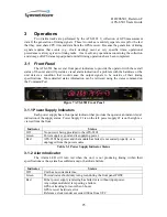
Page 31: ...tatus information can be retrieved using the status command on the Command Port Figure 7 ATS 6501 Front Panel 3 1 1 Power Supply Indicators Each power supply has a front panel indicator that provides the operator an instant visual indication of the supply status Power Supply 1 is on the left power supply 2 is on the right as viewed from the front Indicator Status Off No power is being provided to ...

Page 32: ...A and the 10MHz signal from the reference is available on the 10Mhz In connector Red POST only Table 3 3 Oscillator Locked Indicator 3 1 4 GPS Tracking Indicator The TRACKING GPS light indicates whether the unit is collecting data from enough GPS satellites to calculate a position and time solution If the light is green then the GPS data is being used in steering the frequency reference If it is n...

Page 33: ...utputs Enabled Indicator This indicator provides the operator a visual indication regarding the output modules installed in the rear card slots on the unit No user set up is required and the system will automatically configure the internal monitoring based on the card installed in each slot To determine which module s is causing the alarm use the status health output_modules command Indicator Stat...

Page 34: ...ommand Make sure to save the system settings ATS 6501 frontpanel_button 0 OK ATS 6501 settings hardware enable_fp_button false 3 2 Rear Panel All hardware interfaces and connectors are located on the rear panel of the ATS 6501 The system can provide seven types of timing signals 1 PPS 10 MHz 5MHz DC IRIG AM IRIG NASA36 and the ATS 6511 reference signals depending on which output modules are instal...

Page 35: ...nna to the system The 10MHz IN connector is used to provide the 10MHz signal input from an external frequency reference See Figure 9 Figure 9 Rear Panel Connections Note The Fiber Optic Connection is not currently enabled and is available for expanding the system s capabilities in the future 3 3 Software 3 3 1 Current Version ATS 6501 Users can obtain the current software version via the command p...

Page 36: ...new software onto the flash Once the software has successfully been updated the system will automatically reboot The system network and user configuration files will be saved and reloaded onto the new software image and do not require any additional steps To update the system with the new software 1 FTP into the system and log in username ftp password ftp 2 Switch to binary transfer mode if needed...

Page 37: ...s Once the oscillator lock light is on it should take about 1 minute to begin tracking GPS and the front panel clock to come back It will take an additional 1 5 to 2 minutes for NTP to lock and for the outputs to be enabled Note Users can obtain the new software image from Symmetricom ftp ftp timing com pub ATS 6501 If the software update is not applied and the unit is rebooted or power cycled use...

Page 38: ...Data Port 1135 Certain applications require that GPS data be retrieved in a timely manner For this purpose Port 1135 may be configured to provide real time data output Users can specify which logs are output and users may request any of the ASCII logs specified in the user manual for the Novatel OEMV receiver http www novatel com support docupdates htm oemv 3 4 3 2 Command Port 1700 System command...

Page 39: ...gs from file s on the disk log ftp rt type Add a GPS log User must specify if the log is for ftp or real time rt logs and the log type desired from the Novatel receiver log_compression Enable or disable GZIP compression for the ftp log files 0 Off 1 On log_enable ftp rt Enable or disable GPS logging Specify ftp or real time rt then off on 0 Off 1 On log_filename Set name pattern of log files log_f...

Page 40: ...f the unit via the OP001 Console Cable The ATS 6501 is a DTE device utilizing the RS232 communication protocol Settings for the port are 115 200 baud 8 data bits 1 stop bit no parity and no flow control It is sometimes necessary to access the system via the USB port because the ATS 6501 may not be accessible via the network until the IP Address has been set 3 4 3 3 Diagnostic Port 1800 The ATS 650...

Page 41: ...provided by the status port to update their displays in real time See Appendix C for an example of the data provided by the status port 3 4 4 File Transfer Protocol FTP Allows users to Obtain the FTP log files and the RINEX files The gps log files are available in the ftp user s home directory and the rinex files are available in the rinex subdirectory Users can get to these files using the change...

Page 42: ... if the user simply wanted to get the information on this system type status tflex ATS 6501 status tflex network MAC 00 30 96 00 00 98 broadcast 192 168 1 255 default_gateway 192 168 1 1 ip 192 168 1 253 netmask 255 255 255 0 serial_number SP00235 start 2009 06 04 22 46 uptime 15 hours 29 minutes 44 seconds ver tflex 3 6 2 Users can further refine the requested data fields by adding the desired in...

Page 43: ...nged log IONO UTC data rawalma onchanged log almanac on startup rangea ontime 60 L1 L2 observations 60 seconds C Set the interval for the log file to the desired value using the log_interval command Log interval value is in minutes and can be between 1 and 30 minutes Default is 15 minutes ATS 6501 log_interval 15 OK D Set the maximum number of log files for the system to hold in memory using the l...

Page 44: ...rrently logging data and you change the file naming convention you may wipe out any saved files stored in memory Ensure these files are downloaded prior to making any changes to prevent a possible loss of data F If file compression is desired use the log_compression command and turn the compression on 1 or off 0 Default is on 1 ATS 6501 log_compression 0 Compression Off OK Note When using compress...

Page 45: ...igits 3 prefix user suffix nov type timestamp interval 15 log_selection bestposa ontime 7200 ionutca ontime 7200 rangea ontime 60 rawalma onchanged rawephema onchanged rxhwlevelsa ontime 60 Once the desired changes are made save the set up using the save_logs ftp command ATS 6501 save_logs ftp OK Note If you do not save the setup the system will come back up with the factory defaults when the syst...

Page 46: ...dcast ephemerides waas9a onchanged log WAAS data C If needed turn the real time logging on using the log_enable rt command ATS 6501 log_enable rt 1 D You can verify the real time log settings using the settings gps_logging rt command ATS 6501 settings gps_logging rt enable true log_selection timea ontime 1 waas9a onchanged E The data requested will now be available on port 1135 Users can make chan...

Page 47: ... IOR 131 65 5 0 50 IORW 126 25 0 50 PANAMSAT 135 133 0 50 TELESAT 138 107 3 0 50 ARTEMIS 124 21 5 0 50 3 8 System Verification After the system installation and setup are complete users can verify the system is operating properly by looking at several of the system operating parameters to verify the values are correct If there are no red LEDs lit on the front panel the system is operating correctl...

Page 48: ...hen no satellites are being tracked Wait ten minutes after the Oscillator Lock light is Green to give the system a chance to acquire satellites If the value is still 0 ten minutes after the Oscillator Lock light turned green then there is likely a problem with the antenna setup If you are using the manual position mode and the system is reporting satellites but the GPS Tracking indicator is off th...

Page 49: ...4385A slots 1 ports 1 status good 2 status good 3 status good 4 status good power enabled type 4394A 2 type empty 3 6 Note Slots 3 6 will display information as shown for slots 1 2 based on which slots have cards in them and what type of cards are installed If a card is not installed the type will be empty G Each of the conditions monitored by the system health functions should report false and ha...

Page 50: ...GPS Errors recorded when the unit first starts up may be reported if so they will always have a date of 1 Jan 1998 H Each output modules 1 6 should have zero active errors and the outputs disabled and outputs unlocked active blocks should be zero The power supply 0 1 active blocks should also be zero output_modules 1 active false occurrences 0 2 active false occurrences 0 3 active false occurrence...

Page 51: ...K The system should show that NTP is locked true and that the system is using the internal clock REFCLK 25 0 ntp locked true source REFCLK 25 0 L The system will also show if the external internal clocks have been detected the outputs should be enabled and the system will provide the internal operating temperature If an external 10MHz signal is not being provided the oscillator external field will...

Page 52: ...nna_delay 0 000000000000000e 00 antenna_voltage 0 000000000000000e 00 datum wgs84 mask_angle 1 000000000000000e 01 positioning auto_hours 1 200000000000000e 01 manual_position altitude 1 592729000000000e 03 latitude 4 001941422777778e 01 longitude 1 052390962444445e 02 mode auto gps_logging ftp compression true enable true file_count 100 filename digits 3 prefix user suffix nov type timestamp inte...

Page 53: ...nal_word 0 type irig 4 format B signal_word 0 type irig 2 tsc4373 ports 1 pps_period 1 pps_width 1 000000000000000e 04 type pps 2 pps_period 1 pps_width 1 000000000000000e 04 type pps 3 format B signal_word 0 type irig 4 format B signal_word 0 type irig 3 tsc4395 ports 1 enabled true 2 enabled true 3 enabled true 4 enabled true 5 tsc4387 ports 1 format B signal_word 120 type irig 2 format B ...

Page 54: ...xpired If in the auto positioning mode the rinex file will be available after the auto_positioning period has expired Q If operations are normal and the setup is proper type save at the command prompt to save the system default settings or save filename to save the settings to a different configuration file Use the save_logs ftp and save_logs rt commands to save the ftp or real time logging defaul...

Page 55: ...clock This D A output is then filtered and distributed to the four outputs of the plug in card The FPGA which is clocked by the 100 MHz TCXO provides 1 PPS and serial time codes which are used by the 1 PPS DC IRIG and AM IRIG cards to produce 1 PPS and IRIG time codes The GPS receiver locks its internal reference to the 10MHz signal provided by the OCXO frequency reference A 1 PPS signal is then g...

Page 56: ...e storage area A total of 16 MB is dedicated to the storage of ionospheric logs and as storage capacity is approached older logs will be deleted to make room for newer logs Real time logs are logs requested by the user for output to the Ethernet port on the rear panel of the ATS 6501 They are provided to the user in a timely manner but are not stored on the system All logs must be enabled at start...

Page 57: ...and using the PPS received from the GPS receiver to continuously steer the CPU clock If the unit has been powered off for a long period of time the CPU time may be multiple seconds off In these cases a coarse adjustment of system time is performed and then the startup sequence is restarted This process should only happen once and only in cases where the system has been powered off The Time Code ge...

Page 58: ...ng an internal inspection of the ATS 6501 1 Shut the system down 2 Remove the top of the ATS 6501 3 Visually inspect the various components and make sure that an excessive amount of dust is not present Excessive dust can be removed by using compressed air or vacuum cleaner to clean the electrical components of any accumulated dust 4 Use a vacuum cleaner to clean the fan filter of any accumulated d...

Page 59: ...mulating dust inside the unit as well and allows the fans to provide the proper level of cooling for the internal components It is important to keep this filter clean to allow the proper level of air flow to prevent the system from overheating To clean the filter 1 Remove the fan assembly from the front by loosening the two captive screws 2 Remove the filter from the fan assembly 3 Use a vacuum cl...

Page 60: ...d to the reference GPS has not been not tracking for at least 6 hours or there is a hardware error Reference clock wander has exceeded 100ns from UTC The Rubidium is unlocked Over temperature 65 C External Reference o System is unable to communicate with the external reference source o 10MHz input from the external reference is missing If the alarm light is on users can determine the exact cause o...

Page 61: ...e events in the system using the status health power_supply commands to check on events that occurred earlier ATS 6501 status health power_supply 1 active false occurrences 0 2 active false cleared what No errors when 2008 10 06 16 14 38 874 occurrences 1 set what AC DC supply missing or hardware error when 2008 10 06 16 12 51 346 6 2 2 Outputs Enabled This indicator will turn off if the ATS 6501 ...

Page 62: ...tive true occurrences 1 2 active false occurrences 0 3 active false occurrences 0 4 active false occurrences 0 5 active false occurrences 0 6 active false occurrences 0 6 2 3 GPS Performance There are several factors that could impact the performance of the GPS receiver 6 2 3 1 Poor GPS Receiver Performance There are several issues that can cause poor performance with the GPS receiver This may be ...

Page 63: ...tings gps mask_angle command Default 10 degrees ATS 6501 settings gps mask_angle 1 0000000000000000e 01 Ensure you are using the correct positioning datum o Default is WGS84 o System is capable of using the NAD 83 datum o Ensure any manually entered position is using the correct datum using the settings gps datum command ATS 6501 settings gps datum wgs84 6 2 3 2 GPS Not Tracking This indictor will...

Page 64: ... lightning protection device has been installed in the RF DC path ensure the device has not failed and is not open no continuity o Bad Cable The cable may have failed due to exposure to the weather kinking or bending Inspect the antenna cable and correct any issues and replace any cables that appear to be weathered o Improper Antenna Cable The cable may be either too long or the improper type Symm...

Page 65: ...occurrences 0 clock_wander active false occurrences 0 ATS 6501 status oscillator external locked internal locked lns locked locked true Users can also check the status of the time scale to ensure the UTC offset value ptd is under 100nSec from UTC and the clock is being steered ATS 6501 status kas2 antenna_delay 1 878000000000000e 08 frequency 5 116576335241098e 01 frequency_aging 1 726953124522067...

Page 66: ...in the status oscillator command The front panel Alarm light will be RED and the Oscillator Lock light will be OFF ATS 6501 status oscillator external signal missing internal locked lns locked locked false When the 10Mhz signal is restored the Alarm light will remain on the Oscillator lock light will remain out and the GPS Tracking indicator will go out for 30 seconds Once the GPS Tracking indicat...

Page 67: ... NTP Server use the status ntp command If the NTP Server is operating properly the user will see the following ATS 6501 status ntp locked true source REFCLK 25 0 6 2 7 PTD Value is Noisy The PTD UTC Offset value will be much noisier when the ATS 6501 is in the dynamic mode and during the positioning period while in the AUTO mode Static position users should use the AUTO mode when the antenna posit...

Page 68: ...s 0 The ATS 6501 monitors the fans on the front panel to ensure they are operating to check the current status of the fans use the status fan command Both fans should show a status of 1 indicating it is operating normally ATS 6501 status fan 1 true 2 true Users can look to see if the unit had any issues with either of the fans by using the status health fan command ATS 6501 status health fan 1 act...

Page 69: ...ot to verify the card status ports 1 status good 2 status good 3 status good 4 status good power enabled type 4394A 6 2 10 IRIG Outputs The ATS 6501 is capable of providing different DC IRIG outputs on each port of the 4394A card and AM IRIG outputs on the 4387A card By default ports 3 and 4 on the 4394A card are set to B000 The 4387A outputs are set to B120 by default Users can modify these setti...

Page 70: ...ype 4387A 6 2 11 NASA36 Outputs The ATS 6501 is capable of providing NASA 36 Time Code outputs on each port of the 4387A AM IRIG card The 4387A outputs are set to IRIG B120 by default Users can modify these settings Users are cautioned to ensure they connect the correct cables to the correct output ports to avoid any problems To verify the settings use the settings hardware outputs slots N command...

Page 71: ...t it should switch to those displays and give the local operator the IP Address If not the IP Address was not set it will not display the IP Address and the unit will assign an IP Address of 0 0 0 0 Plug the LAN Connector into the rear of the unit and if a DHCP server is available the unit should obtain an IP Address o Power cycle the unit Static o Verify the static IP address Netmask Broadcast IP...

Page 72: ...ared Jan 1 00 02 52 tflex 495 985 0x392700 Alarm output_modules 3 cleared Jan 1 00 02 52 tflex 495 996 0x392700 Alarm output_modules 4 cleared Jan 1 00 02 53 tflex 495 010 0x392700 Alarm output_modules 5 cleared Jan 1 00 02 53 tflex 495 029 0x392700 Alarm output_modules 6 cleared Jan 1 00 02 53 tflex 495 043 0x392700 Alarm power_supply 1 cleared Jan 1 00 02 53 tflex 495 056 0x392700 Alarm power_su...

Page 73: ...e 50 Ω Timing Performance UTC USNO Offset w GPS Precise Calibration 15 ns RMS Coarse Calibration 100 ns RMS Allan Deviation Locked to GPS 1s 5E 12 10s 5E 12 100s 5E 12 Frequency Accuracy 1e 11 one day Holdover Accuracy 10Mhz Output 5E 11 month Ethernet Interface Quantity 1 Connector RJ 45 Protocol TCP IP Speed 10 100 Base T Network Time Protocol NTP Server Stratum Level 0 Level 1 when locked to GP...

Page 74: ...ed 10dB PPS DC IRIG Module 4394A Characteristic Description Number of outputs Four Output connectors BNC F Impedance 50 Ω Signals PPS 2 DC IRIG 2 PPS Intervals Default 1PPS Valid PPS values are 1M 100K 10K 1K 100 10 1 Levels 1V RMS into 50 Ω Pulse Width Default 100us 10us Pulse width is variable in integer counts of 100MHz clock period Rise Time 15ns Jitter 200ps Skew 2ns DC IRIG Default B000 Type...

Page 75: ...mately 10 dBm after which an alarm is raised Characteristic Description Number of outputs Four Output connectors BNC F Impedance 50 Ω Amplitude 13dbm 2dBm Signal Sine Wave Harmonic 40dbc Phase Noise 1 Hz 100dbc Hz 10 Hz 125dbc Hz 100Hz 132dbc Hz 1KHz 138dbc Hz 10KHz 141dbc Hz 100Khz 141dbc Hz Amplitude Modulated AM IRIG Module 4387A Characteristic Description Number of outputs Four Output connecto...

Page 76: ... from multiple ATS 6511s connected to a TSC 4340A connected to this output AC Power Supply 4385A 100 240 V AC 50 60 Hz 75A Power Mains Fuse AC Input Two 250 V 1 A T Time delay 5 x 20 mm DC Power Supply 4886A 48 VDC SELV type Power Inlet Type DC input Mates with 3 pin Amp Part 1 350346 0 connector with female sockets Amp Part 925661 1 Power Supply Cord Set DC input Minimum 1 5 mm 14 AWG with a 15A ...

Page 77: ...sition alt 4 8305500000000002e 01 Ellipsoid Height fixed false Auto position information lat 3 8466278665490002e 01 Latitude lon 7 7440859995379995e 01 Longitude satellite Satellite Information number 7 Number of satellites tracked signal avg 4 5854572296142578e 01 Average signal strength desc Good Signal Quality enum 2 Diagnostic value freq dual Tracking L1 only Single or L1 L2 max 4 966400146484...

Page 78: ... Clock Steer command failures active false Event currently active true occurrences 0 Number of events clock_wander Clock Wander active false Event currently active true occurrences 0 Number of events fan Fan Failures 1 Left Fan active false Event currently active true occurrences 0 Number of events 2 Right Fan active false Event currently active true occurrences 0 Number of events gps_error GPS Re...

Page 79: ... 2 Right Power Supply active false true Active alarm occurrences 0 Number of events ref_unlocked Reference unlocked alarm active false true Active alarm cleared Status set 1 cleared 0 what Rb and LNS are locked Description of last event when 1998 01 01 00 02 42 563 Date Time of the event occurrences 1 Number of Events set Shows last active alarm what LNS is unlocked Description of the alarm when 1...

Page 80: ...55 255 0 Current Netmask serial_number SP00220 Serial Number start 2008 10 02 17 49 Date Time of last restart uptime 2 hours 2 minutes 54 seconds Total time systems been up ver 3 4 2 Software version time 2009 10 02 19 52 03 Time status data requested System Errors Alarms and events on the ATS 6501 are available via the status command As the events occur the system will set the alarm and time Once...

Page 81: ... positioning manual_position longitude 1 052390962444445e 02 2009 12 27 23 06 58 514 settings gps positioning mode auto 2009 12 27 23 06 58 539 settings gps_logging ftp compression 1 2009 12 27 23 06 58 552 settings gps_logging ftp enable 1 2009 12 27 23 06 58 567 settings gps_logging ftp file_count 100 2009 12 27 23 06 58 576 settings gps_logging ftp filename digits 3 2009 12 27 23 06 58 584 sett...

Page 82: ...rig 2009 12 27 23 06 58 906 settings hardware outputs slots 5 tsc4387 ports 2 format B 2009 12 27 23 06 58 913 settings hardware outputs slots 5 tsc4387 ports 2 signal_word 120 2009 12 27 23 06 58 920 settings hardware outputs slots 5 tsc4387 ports 2 type irig 2009 12 27 23 06 58 928 settings hardware outputs slots 5 tsc4387 ports 3 format B 2009 12 27 23 06 58 936 settings hardware outputs slots ...

Page 83: ...wer enabled 2009 12 27 23 06 37 132 status hardware outputs slots 6 type 4372A 2009 12 27 23 06 18 248 status hardware power numsupplies 2 2009 12 27 23 06 38 185 status hardware power supplies 1 status good 2009 12 27 23 06 38 181 status hardware power supplies 1 type 4385A 2009 12 27 23 06 38 210 status hardware power supplies 2 status good 2009 12 27 23 06 38 207 status hardware power supplies ...

Page 84: ...464e 10 2009 12 27 23 08 50 412 status ntp locked 1 2009 12 27 23 07 48 743 status ntp source REFCLK 25 0 2009 12 27 23 06 37 436 status oscillator external signal missing 2009 12 27 23 06 37 428 status oscillator internal locked 2009 12 27 23 06 37 442 status oscillator lns locked 2009 12 27 23 06 37 450 status oscillator locked 1 2009 12 27 23 08 48 865 status outputs enabled 2009 12 28 18 22 16...

Page 85: ...ber 5 2009 02 10 20 45 55 958 status gps satellite signal min 4 702999877929688e 01 2009 02 10 20 45 55 963 status gps satellite signal max 4 985499954223633e 01 2009 02 10 20 45 55 975 status gps satellite signal avg 4 883119964599609e 01 2009 02 10 20 45 55 984 status gps satellite signal desc Good 2009 02 10 20 45 55 988 status gps satellite signal enum 2 2009 02 10 20 45 58 007 status gps mode...

Page 86: ...and strictly enforced and the user will be informed they attempted to use an illegal filename If the system cannot recognize the configuration status network or settings parameter the operator is requesting it may return no info Make sure the fields were typed correctly for the data you are attempting to retrieve Command Arguments Any arguments contained are optional and can be left out if desired...

Page 87: ...voltage 0 0000000000000000e 00 0V 5 0000000000000000e 00 5VDC 1 2000000000000000e 01 12VDC Clear Alarms Description Clears any latched alarm events from the alarm list and front panel This allows the operator to acknowledge a system alarm and clear it from the status message status alarm and clear the front panel alarm light If any additional alarms events occur the new alarm will be added to the ...

Page 88: ... filename the system will indicate the user is attempting to delete a file with an illegal filename Syntax delete filename Command Example ATS 6501 delete test Query ATS 6501 list This command lists all of the current system configuration files saved by the user Delete_logs Description Deletes the user specified ftp or real time rt gps logging configuration file In the example below the user is de...

Page 89: ...70 info Diag_port Description Switches the current telnet session from the Command Port 1700 to the Diagnostic Port 1800 Syntax diag_port Command Example ATS 6501 diag_port To end this session and return to the command port type quit and press enter Fix Position Description Sets the ATS 6501 position to the current GPS coordinates current or to the settings entered by the user nf When entering the...

Page 90: ...0 This feature is enabled by default 1 Syntax frontpanel_button 0 1 Command Example ATS 6501 frontpanel_button 0 Query ATS 6501 settings hardware enable_fp_button false true enabled false disabled Help Description Displays the entire command list or will provide details on the specified command command Acceptable shortcuts are h or a Syntax help command Command Examples ATS 6501 help command ATS 6...

Page 91: ...here must be preceded with a sign or followed with a S Default is the northern hemisphere Syntax latitude nf Note Once this command is executed the positioning mode will be manual and the longitude and altitude values in the manual gps settings will be in effect Command Examples ATS 6501 latitude 38 466279772 ATS 6501 latitude 38 466279772N ATS 6501 latitude 38 466279772 ATS 6501 latitude 38 46627...

Page 92: ...ating the file does not exist The system will not accept files named with illegal characters and if any illegal characters are specified in the filename the system will indicate the user is attempting to load a file with an illegal filename Syntax load filename Command Example ATS 6501 load test Query ATS 6501 list default test Load_logs Description Loads the user specified ftp or real time rt gps...

Page 93: ... rt ionutca ontime 7200 ionutca ontime 7200 is the novalog command Query ATS 6501 settings gps_logging ftp log_selection ionutca ontime 7200 Log Compression Description User can opt to compress 1 the log ftp log files or leave these files uncompressed 0 Syntax log_compression 0 1 Note When using the log_filename setting of timescale the gz extension will be appended to the filename When using the ...

Page 94: ...o digits of the year two digit month two digit day two digit hour and two digit minute when the log was opened Example File 0810021530 log was opened 2 Oct 2008 at 15 30 UTC This command will also accept an optional suffix to append to the filename i e nov 0810021530 nov Note When using this option the prefix and digits values that apply for the user filename settings have no impact on the filenam...

Page 95: ... value is lower than the number of log files currently in storage If so the system will delete as many log files as needed to drop the number of logs to the new value starting with the oldest file and working forward Command Example ATS 6501 log_number 15 Query ATS 6501 settings gps_logging ftp file_count 15 Longitude Description Sets the ATS 6501 longitude The ATS 6501 will respond with OK when t...

Page 96: ...le 1 000000000000000e 01 Nasa36 Description Allows the operator to select the NASA36 on any of the AM IRIG outputs on the 4387A Output card The ATS 6501 will respond with OK when the settings have been accepted The system will generate an error message if the operator attempts to enter an unsupported or invalid Time Code Syntax nasa36 slot port Command Examples ATS 6501 nasa36 5 2 Query ATS 6501 s...

Page 97: ...he mode for setting the IP Address DHCP static and assigning the network settings when using a static IP Address Syntax network_config mode DHCP static ip IP Address mask netmask broadcast Broadcast IP gateway Gateway IP Command Example ATS 6501 network_config mode static ip 192 168 1 50 mask 255 255 255 0 broadcast 192 168 1 255 gateway 192 168 1 1 Note These network settings will take effect imm...

Page 98: ...ry ATS 6501 settings gps positioning auto_hours 10 Note If the system starts up in auto mode or is switched into the auto mode from dymanic or manual the system will begin averaging over this period to determine the position While the system is performing this function a countdown timer will show how much time remains before the system determines and fixes its position status gps auto_positioning ...

Page 99: ...ent telnet session ATS 6501 prompt enable 0 Prompt is no longer visible This change is only in effect for the current telnet session Command Example This command makes it the system default ATS 6501 prompt text Test default ATS 6501 Note Prompt does not change until the next command port connection is made ATS 6501 prompt enable 0 default ATS 6501 Prompt is still visible Prompt does not disappear ...

Page 100: ...ce source external Warning Prior to setting the reference to external make sure the 10MHz signal from the external reference is plugged in to the 10Mhz IN connector on the rear of the ATS 6501 Reference Type Description Allows the user to set the type of external reference to be used hp5071a is the default setting The ATS 6501 is capable of communicating with the Symmetricom 5071A and will check t...

Page 101: ...s attempting to load a file with an illegal filename Syntax save filename Command Example ATS 6501 save test Query ATS 6501 list default test Save_logs Description Saves the user specified ftp or real time rt GPS logging configuration file The user can save the default system GPS logging settings by typing save ftp rt and pressing enter The users can save other system configurations as desired by ...

Page 102: ...ftware Update Description Updates the ATS 6501 system software using a previously uploaded iso image file Syntax software_update Command Example ATS 6501 software_update filename Note If the iso image is not on the system the command will attempt to execute display a line feed and the system will return to the command prompt If this occurs the iso file must be uploaded to the system before the sof...

Page 103: ...501 syslog error Unlog Description Allows the user to remove log files type from the FTP files and real time data on port 1135 Users specify the log type ftp rt and the Novatel OEMV type to remove Users can also use the keyword all to remove all user specified log types Syntax unlog ftp rt log all Command Example ATS 6501 unlog ftp waas9a waas9a type Query ATS 6501 settings gps_logging ftp log_sel...

Page 104: ...224 255 285 316 346 13 013 044 072 103 133 164 194 225 256 286 317 347 14 014 045 073 104 134 165 195 226 257 287 318 348 15 015 046 074 105 135 166 196 227 258 288 319 349 16 016 047 075 106 136 167 197 228 259 289 320 350 17 017 048 076 107 137 168 198 229 260 290 321 351 18 018 049 077 108 138 169 199 230 261 291 322 352 19 019 050 078 109 139 170 200 231 262 292 323 353 20 020 051 079 110 140 ...

Page 105: ...3 013 044 073 104 134 165 195 226 257 287 318 348 14 014 045 074 105 135 166 196 227 258 288 319 349 15 015 046 075 106 136 167 197 228 259 289 320 350 16 016 047 076 107 137 168 198 229 260 290 321 351 17 017 048 077 108 138 169 199 230 261 291 322 352 18 018 049 078 109 139 170 200 231 262 292 323 353 19 019 050 079 110 140 171 201 232 263 293 324 354 20 020 051 080 111 141 172 202 233 264 294 3...

Page 106: ...DOC06501_Revision F ATS 6501 Users Guide 100 Appendix F Certificate of Compliance ...

Reviews: