4-11
Cisco AS5350 and Cisco AS5400 Universal Gateway Software Configuration Guide
OL-3418-02 B0
Chapter 4
Continuing Configuration Using the Command-Line Interface
Configuring Alarms
Verify
To see the status of the alarms, enter the show facility-alarm command:
AS5350# show facility-alarm
Device State
------ -----
FastEthernet0/0 UP
Modem Card 4 UP
Facility Alarm is ON
Tip
If you are having trouble:
•
Make sure the cable connections are not loose or disconnected.
•
Make sure you are using Number 12 or 14 AWG copper wires to connect to the alarm port terminal
blocks.
•
Make sure your alarm is operational.
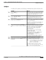
Step 3
AS5350(config)# facility-alarm detect
interface [interface type] [slot/port]
Turns on the facility alarm when an interface goes
down. Enter interface type and slot/port
designation.
Step 4
AS5350(config)# facility-alarm detect
controller [t1 | e1 | t3] [slot/port]
Turns on alarm when controller goes down. The
slot values range from 1 to 7. The port values
range from 0 to 7 for T1 and E1. For T3, the port
value is always 0.
Step 5
AS5350(config)# facility-alarm detect
modem-board [slot]
Turns on alarm when modem board present in slot
# fails.
Step 6
AS5350(config)# facility-alarm detect rps
Turns on alarm when RPS failure event is
detected. Any of the following failures turns on
the alarm:
•
I/P voltage failure
•
O/P voltage failure
•
Overvoltage condition
•
Multiple failures
Step 7
AS5350(config)# facility-alarm detect
temperature
Turns on alarm if thermal failure event is detected.
Step 8
AS5350(config)# facility-alarm detect fan
Turns on alarm if fan failure event is detected.
Step 9
AS5350(config-if)# Ctrl-Z
AS5350#
Returns to enable mode.
Command
Purpose


