5 Implementation of EtherNet/IP
5.3 VSC-Vendor Specific Classes
XI/ON: XNE-GWBR-2ETH-IP
09/2011 MN05002007Z-EN
www.eaton.com
131
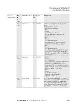
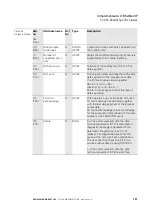
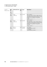
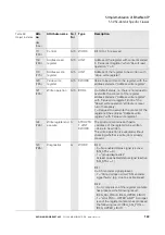
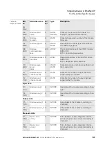
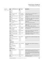
113
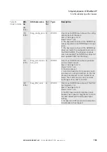
(71h)
Result write oper-
ation
G
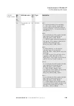
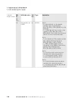
Bit 0 to 5:
reserved
Bit 6:
– 0 = No modification of the data in the
register bank by process output, i.e.
WRITE OPERATION = 0. A write job
would be accepted with the next telegram
of process output data. (handshake for
data transmission to the register.)
– 1 = "control register write acknowledged"
A modification of the register contents by
a process output was initiated, i.e.
WRITE OPERATION = 1. A write job
would not be accepted with the next tele-
gram of process output data.
Bit 7:
– 0 = The writing of user data for process
output to the register addressed with
"Address write register" in the process
output data could not be executed.
– 1 = "control register write accepted" The
writing of user data for process output to
the register addressed with "Address
write register" in the process output data
could be executed successfully.
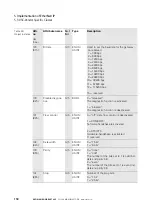
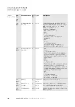
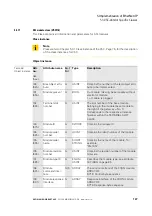
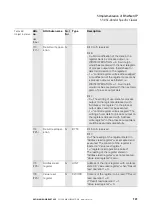
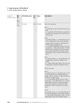
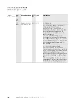
114
(72h)
Result read oper-
ation
G
BYTE
Bit 0 to 6: reserved
Bit 7:
0 = The reading of the register stated in
"Address read register" was accepted and
executed. The content of the register is
located in "Value read register".
1 = "register read operation aborted"
The reading of the register stated in
"Address read register" was not accepted.
"Value read register" is zero.
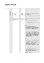
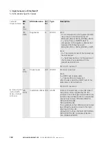
115
(73h)
Address read
register
G
UINT
Address of the input register with contents
stated in "Value read register" when "Result
read operation" = 0.
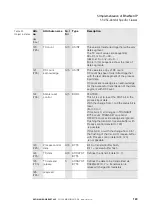
116
(74h)
Value read
register
G
DWORD
Content of the register to be read if "Result
read operation" = 0.
If "Result read operation" = 1,
"Value read register" = 0.
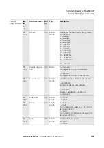
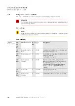
Table 58:
Object instance
Attr.
no.
dec.
(hex.)
Attribute name
G
et/
S
et
Type
Description

