16
IV. THEORY OF OPERATION
4.1 Introduction
This section describes the circuitry of the DKB-2010 keyboard system and explains its operation, first in
general terms and then in detail.
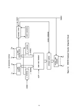
A block diagram of the system is provided in Figure 8.1, bound in Section 8 with the schematic diagrams
of the keyboard circuitry. The drawing symbols and conventions used are illustrated in Figure 8.2.
The keyboard uses integrated digital logic circuitry throughout. Readers unfamiliar with the principles of
logic circuits may find it helpful to refer to an introductory discussion of The subject before proceeding
4.2 General Operating Principles
The primary function of the keyboard circuits is to convert the closure of a keyswitch into a series of
sequential pulses-marks and spaces in the RTTY mode, or dots and dashes in the Morse mode. These pulses
appear at the keyboard output stages, where they activate switching transistors to key the station loop
circuit or CW transmitter.
Of the 53 independent keyswitches, 46 are arranged in a matrix. The remaining seven are used for
special functions. The 46 matrix keys are connected to a large-scale integrated-circuit keyencoder.
Whenever this circuit senses closure of a keyswitch, it produces a seven-bit digital code, which appears in
parallel form at the circuit's output. This code is the ASCII equivalent
of the character to be transmitted.
Some of the keyswitches can produce two different characters. One of these characters is printed on the
lower half of the keytop. Those appearing on the upper half are "shifted" characters, transmitted by
pressing one of the shift keys along with the character key. Closure of the shift keyswitch instructs the
keyencoder to produce the ASCII code for the shifted rather than the unshifted character.
Of the seven keys not connected to the matrix, two are the shift keys just mentioned. Four others are
used to initiate special character sequences: the station identifier message, the "quick brown fox" test
signal, and the special three-character memory sequences. The remaining key, labeled BREAK, allows the
operator to break the RTTY loop manually, or, in the Morse mode, to key the transmitter manually for
tuning.
The ASCII code produced by the keyencoder or one of the special message generators must be
converted to a different pattern of bits to produce the RTTY or Morse code pulse sequence. The conversion
is accomplished by a read only memory (ROM) preprogrammed with the code patterns required for each
character. The seven-bit code from the keyencoder or the special message generators, along with an eighth
bit which selects the RTTY or Morse mode, is applied to the eight address inputs of the ROM. The input code
addresses a particular eight-bit location in the memory. In that location is stored the correct code for the
character, which appears at the ROM output. Thus the ASCII code is converted to the Morse or RTTY bit
pattern.
The ROM output is fed to an eight-bit buffer memory. If the keyboard is idle, the code is passed directly
to the 10-bit static shift register. If the latter register already contains a character, however, the buffer
stores the code until the shift register is cleared and ready to accept new input data.
Up to this point, all character codes are handled in parallel format (all bits are transmitted simultaneously
on parallel lines). Both the Morse and RTTY transmission modes, however, require that the output pulses
appear sequentially. The 10-bit shift register performs the necessary parallel-to-serial conversion. The input
code bits from the storage buffer are loaded into the shift register in parallel. Clock pulses are then applied
to the register, causing the bits to appear in sequence at the register output.
Applications (Englewood Cliffs, N. J.: Prentice Hall, Inc., 1970).
Table 4.2 in Section 4 lists the ASCII code for each character used in the DKB-2010 keyboard.
Summary of Contents for DKB-2010
Page 1: ......
Page 20: ...18...
Page 39: ...37 Table 4 3 ROM Converter Input and Output Codes...
Page 52: ...50 Figure 6 1 Logic Circuit Board Test Points...
Page 53: ...51 Figure 6 2 Keyswitch Circuit Board Test Points...
Page 54: ...52 Figure 6 3 Power Supply Circuit Board Test Points...
Page 57: ...55 Table 6 4 DKB 2010 Wire List...
Page 63: ...61...
Page 64: ...62...
Page 65: ...63...
Page 67: ...65...
Page 69: ...67...
Page 71: ...69...
Page 73: ...71...
Page 75: ...73...
Page 77: ...75...
Page 79: ...77...
Page 81: ...79...
Page 83: ...81...
Page 85: ...83...
Page 87: ...85...
Page 89: ...87...
Page 91: ...89...
Page 92: ...90...
Page 93: ...91...
Page 94: ...92...
Page 95: ...93...
Page 96: ...A1 EXTENDED MEMORY OPTION FOR THE DKB 2010 KEYBOARD INSTRUCTION MANUAL...
Page 100: ...A5...
Page 101: ...A6...

