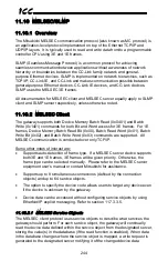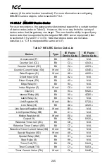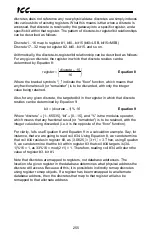
257
ICC
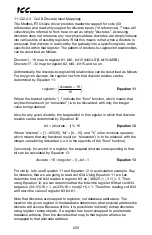
11.12.2.1.3 Register and Discrete Mapping
Holding and Input Registers
Modbus registers are mapped in the database as 2-byte values. This means that
each register in a service object takes up two database addresses. For example
if a service object’s starting register is “1”, the number of registers is “5”, and the
database address is “100”, then registers 1 through 5 will be mapped at database
addresses 100 through 109 (register 1 mapped at address 100 and 101, register
2 mapped at address 102 and 103 and so on).
Coils and Discrete Inputs
Coils and Discrete Inputs, from here on collectively referred to as “discretes”, are
mapped on a bit-by-bit basis in the database starting with the least significant bit
of the database byte. For example, if a service object’s starting discrete is “1”, the
number of discretes is “19”, and the database address is “320”, then discrete 1
through 8 will be mapped to bit 0 through 7, respectively, at address 320, discrete
9 through 16 will be mapped to bit 0 through 7, respectively, at address 321, and
discrete 17 through 19 will be mapped to bit 0 through 2, respectively, at address
322. The remaining 5 bits in the byte at address 322 are unused.
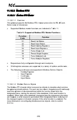
11.12.2.2
Modbus RTU Slave
11.12.2.2.1 Overview
The gateway supports the Modbus RTU slave protocol on its RS-485 port. Some
notes of interest are:
•
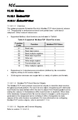
Supported Modbus slave functions are indicated in Table 12.
Table 12: Supported Modbus RTU Slave Functions
Function
Code
Function
01
Read Coil Status
02
Read Input Status
03
Read Holding Registers
04
Read Input Registers
05
Force Single Coil
06
Preset Single Register
08
Diagnostics (Subfunction 0 only)
15
Force Multiple Coils
16
Force Multiple Registers
•
Database data can be accessed as either holding registers (4X references)
or input registers (3X references). For example, accessing database
address 1300 involves accessing holding register 41301 or input register
31301 (i.e. offset 1301).


