147
ICC
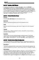
Read Enable and Function Code Selection
Check
Read
to enable reading (the service object will continuously read from the
drive unless a pending
Write
exists). When reads are enabled, the desired read
Function Code
can be selected in the drop-down box. When connected to the
drives via a 2-wire RS-485 network, Toshiba recommends use of the “G” read
function code. When connected to the drives via a 4-wire RS-485 network, either
the “G” or “R” function codes can be used.
Write Enable and Function Code Selection
Check
Write
to enable writing (when values encompassed by this service object
change in the gateway’s database, these changes will be written down to the
targeted drive). When writes are enabled, the desired write
Function Code
can
be selected in the drop-down box. The “P” function code writes to the drive’s
volatile RAM memory only, and is typically used when frequently writing to
configuration parameters in order to prevent damage to the drive’s EEPROM
memory (which has a limited write count lifecycle). The “W” function code writes
to both the drive’s volatile RAM memory as well as its non-volatile EEPROM
memory. Drive command parameters (command word, frequency command etc.)
exist in RAM only, so either write function code can be safely used when writing
to them.
Service Object Status
If it is desired to reflect the status of this service object, check the
Reflect Status
checkbox and enter a database
address
between 0 and 4080 (0x0 – 0xFF0) at
which to store the status information. For more information on reflecting the
status of service objects, refer to section 8.5.2.
8.8.16.3
Configuration Example
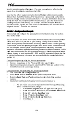
This example will configure the gateway for end-to-end communication using
Toshiba ASD Master and EtherNet/IP Server.
Say, for instance, we wish to communicate to a Toshiba G7 adjustable-speed
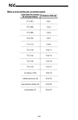
drive from a PLC that supports EtherNet/IP. We wish to monitor the output
frequency, status word, output current, and DC bus voltage of the drive, located
at parameters FE00, FE01, FE03 and FE04, respectively. To run the drive, we
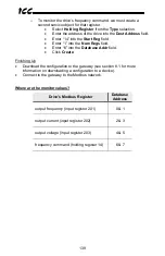
need to be able to write to the RS-485 command word and frequency command,
located at parameters FA04 and FA05, respectively.
Configure the Ethernet port using the above requirements
•
Connect the gateway to the PC via a USB mini type-B cable.
•
Open the configuration utility and select the ETH-1000 (see section 8.1 for
more information on selecting a device).
•
Click on the
Ethernet Configuration
subtab.
•
Click
Use a static IP address
and enter the IP address settings that your
PLC is configured to communicate with.
•
Check the checkbox next to
EtherNet/IP
Server
in the
Protocol
dropdown
menu, and then click on the
EtherNet/IP Server
subtab.
•
Enter “0” into the
Produced Data Start Address
field.


