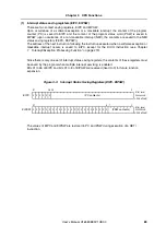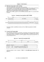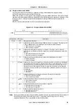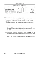
88
Chapter 3
CPU Functions
User’s Manual U16580EE3V1UD00
3.2.2 System
register
set
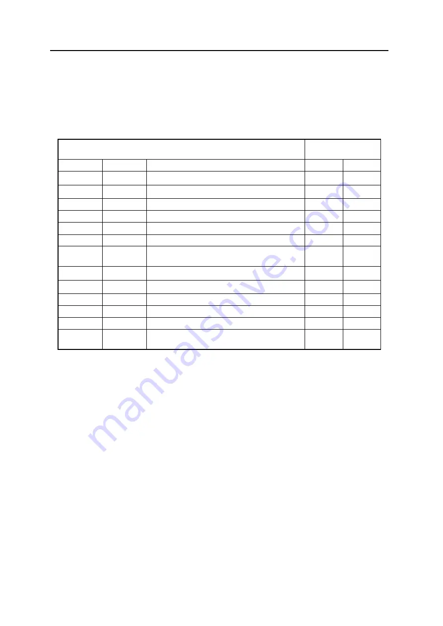
System registers control the status of the CPU and hold interrupt information.
Read from and write to system registers are performed by setting the system register numbers shown
below with the system register load/store instructions (LDSR, STSR instructions).
Notes: 1.
Since only one set of registers is available, the contents of these registers must be saved by
the program when multiple interrupt servicing is enabled.
2.
Since only one set of registers is available, the contents of these registers must be saved by
the program when CALLT instructions nesting is used.
Caution:
Even if bit 0 of EIPC, FEPC, or CTPC is set to (1) by the LDSR instruction, bit 0 is
ignored during return with the RETI instruction following interrupt servicing
(because bit 0 of PC is fixed to 0). If setting a value to EIPC, FEPC, and CTPC, set an
even number (bit 0 = 0).
Table 3-2:
System Register Numbers
System Register
Operand Specification
Enabled for instruction
No.
Name
Function
LDSR
STSR
0
EIPC
PC value at Interrupt handler entry
Note 1
Yes
Yes
1
EIPSW
PSW value at Interrupt handler entry
Note 1
Yes
Yes
2
FEPC
PC value at NMI handler entry
Yes
Yes
3
FEPSW
PSW value at NMI handler entry
Yes
Yes
4
ECR
Exception Cause Register
No
Yes
5
PSW
Program status word
Yes
Yes
6 to 15
-
Reserved numbers for future function expansion
(The operation is not guaranteed if accessed.)
No
No
16
CTPC
PC value at CALLT subroutine entry
Note 2
Yes
Yes
17
CTPSW
PSW value at CALLT subroutine entry
Note 2
Yes
Yes
18
DBPC
PC value at exception/debug trap entry
Yes
Yes
19
DBPSW
PSW value at exception/debug trap entry
Yes
Yes
20
CTBP
CALLT base pointer
Yes
Yes
21 to 31
-
Reserved numbers for future function expansion
(The operation is not guaranteed if accessed.)
No
No
Summary of Contents for V850E/PH2
Page 6: ...6 Preface User s Manual U16580EE3V1UD00...
Page 16: ...16 User s Manual U16580EE3V1UD00...
Page 28: ...28 User s Manual U16580EE3V1UD00...
Page 32: ...32 User s Manual U16580EE3V1UD00...
Page 84: ...84 Chapter 2 Pin Functions User s Manual U16580EE3V1UD00 MEMO...
Page 144: ...144 Chapter 3 CPU Functions User s Manual U16580EE3V1UD00 MEMO...
Page 192: ...192 Chapter 5 Memory Access Control Function PD70F3187 only User s Manual U16580EE3V1UD00 MEMO...
Page 312: ...312 Chapter 9 16 Bit Timer Event Counter P User s Manual U16580EE3V1UD00 MEMO...
Page 534: ...534 Chapter 11 16 bit Timer Event Counter T User s Manual U16580EE3V1UD00...
Page 969: ...969 Chapter 20 Port Functions User s Manual U16580EE3V1UD00 MEMO...
Page 970: ...970 Chapter 20 Port Functions User s Manual U16580EE3V1UD00...
Page 976: ...976 Chapter 22 Internal RAM Parity Check Function User s Manual U16580EE3V1UD00 MEMO...
Page 984: ...984 Chapter 23 On Chip Debug Function OCD User s Manual U16580EE3V1UD00 MEMO...
Page 1006: ...1006 Chapter 24 Flash Memory User s Manual U16580EE3V1UD00 MEMO...
Page 1036: ...1036 Chapter 27 Recommended Soldering Conditions User s Manual U16580EE3V1UD00 MEMO...
Page 1046: ...1046 Appendix A Index User s Manual U16580EE3V1UD00 MEMO...
Page 1052: ...1052 User s Manual U16580EE3V1UD00...
Page 1053: ......


