Copyright © Siemens AG 2010. All rights reserved.
Page
29
ERTEC 400 Manual
Technical data subject to change
Version 1.2.2
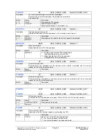
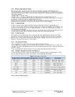
FIQIRR
R
Addr.: 0x5000_0050
Default: 0x0000_0000
Description
FIQ request register
Indication of the fast interrupt requests detected on the basis of a positive edge
Bit No.
Name
Description
7 – 0
FIQIRR
Inputs 0 to 7 of the FIQ interrupt controller
'0'
= No request
'1' = Request is occurred
FIQ_MASKREG
R/W
Addr.: 0x5000_0054
Default: 0x0000_00FF
Description
Interrupt mask register for FIQ
Enable/disable of FIQ interrupt inputs
Bit No.
Name
Description
7 – 0
FIQ_MASKREG
FIQ interrupt input 0 to 7
'0'
= Interrupt input enabled
'1'
= Interrupt input disabled
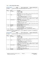
IRREG
R
Addr.: 0x5000_0058
Default: 0x0000_0000
Description
Interrupt request register
Storage of interrupt requests that have occurred
Bit No.
Name
Description
15 – 0
IRREG
Interrupt input 0 to 15
0
=Interrupt request inactive/1=Interrupt request active
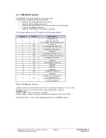
MASKREG
R/W
Addr.: 0x5000_005C
Default: 0x0000_FFFF
Description
Interrupt mask register
Enable/disable of interrupt inputs
Bit No.
Name
Description
15 – 0
MASKREG
Interrupt input 0 to 15
0
=Interrupt input enabled/1=Interrupt input disabled
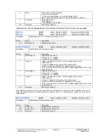
ISREG
R
Addr.: 0x5000_0060
Default: 0x0000_0000
Description
In-service register
Indication of the interrupt requests confirmed by the CPU
Bit No.
Name
Description
15 – 0
ISREG
Interrupt input 0 to 15
0
=Interrupt request not confirmed
1=Interrupt request has been confirmed
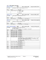
TRIGREG
R/W
Addr.: 0x5000_0064
Default: 0x0000_0000
Description
Trigger select register
Selection of interrupt detection
Bit No.
Name
Description
15 – 0
TRIGREG
Interrupt input 0 to 15
0
=Interrupt detection via edge
1=Interrupt detection via level
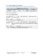
EDGEREG
R/W
Addr.: 0x5000_0068
Default: 0x0000_0000
Description
Edge select register
Edge selection for interrupt detection
(only if edge detection is specified for the associated input)
Bit No.
Name
Description
15 – 0
EDGEREG
Interrupt input 0 to 15
0
=Interrupt detection via positive edge
1
=Interrupt detection via negative edge

