Copyright © Siemens AG 2010. All rights reserved.
Page
74
ERTEC 400 Manual
Technical data subject to change
Version 1.2.2
7 Local Bus Unit (LBU).
The ERTEC 400 can also be operated from an external host processor. Two different bus interfaces are available
for this purpose:
•
PCI bus
•
Local bus unit
The bus system is selected using the CONFIG[2] input pin.
CONFIG[2] = 0 LBU bus system is active
The LBU is a 16-bit data interface.
The following signal pins are available for the LBU on the ERTEC 400.
•
Data bus
16 bit
LBU_DB[15 : 0]
•
Address bus
21 bit
LBU_AB[20 : 0]
•
Memory CS
1
LBU_CS_M_N
•
Register CS
1
LBU_CS_R_N
•
RD/WR config
1
LBU_CFG
•
RD/WR
2
LBU_WR_N / LBU_RD_N
•
Ready
2
LBU_POL_RDY, LBU_RDY_N
•
Byte selection
2
LBU_BE[1 : 0]
•
Page segment selection
2
LBU_SEG[1 : 0]
•
Interrupt outputs
2
LBU_IRQ0_N, LBU_IRQ1_N
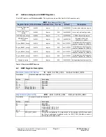
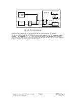
Four different pages within the ERTEC 400 can be accessed via the LBU.
Each page can be set individually.
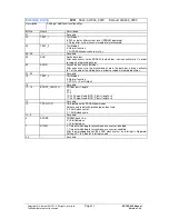
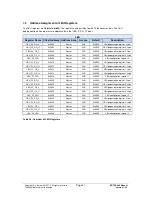
The settings for the four pages are made via the LBU page registers. Five page registers are available per page.
These registers are used for the size, offset, and access width settings of the page. The "LBU_CS_R_N" chip
select signal can be used to access the page registers.
The following settings are possible for each page:
•
Access size of a page between 256 bytes and 2 Mbytes with 2-page range register
•
Offset (segment) of page in 4-Gbyte address area with 2-page offset register
•
Access type (data bit width) with 1 page control register
The ERTEC 400-internal address area is accessed via the “LBU_CS_M_N” chip select signal.
The LBU supports accesses to the address area with two separate read and write cables or with a common
read/write cable. The access type setting is made via the “LBU_CFG” input. The polarity of the ready signal is set
via the “LBU_POL_RDY” input.
LBU_POL_RDY
LBU_RDY
0
Low active
1
High active
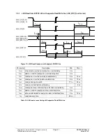
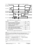
LBU_RDY_N is a tristate output and must be pulled to his “ready” level by an external pull-down or pull-up
resistor. During an access from the LBU-Interface to the ERTEC 400 (CS with RD or WR activ) , the
LBU_RDY_N switched to inactiv (Wait) first. LBU_RDY_N will be active for a 50 MHz-Clock if data can be read or
write. After that LBU_RDY_N switched back to tristate. The external Pull- (up/down) resistor drives the ready
state.
The four segments are addressed via the two LBU_SEG[1:0] inputs.
LBU_SEG[1 : 0]
Addressed Segment
00
LBU_PAGE0
01
LBU_PAGE1
10
LBU_PAGE2
11
LBU_PAGE3

