54
4. Detection method: the reference method for detecting whether the robot is at the
reference point. There is a command position or current position.
5. Output IO when entering the area: enter the area to output low level, otherwise
output high level.
6. Input IO when the external device enters: the motion stops when the external
device inputs a low level, and the motion continues when the external device inputs a high
level (Note: this function is not applicable to the positioner).
7. Note: make a note for the current interference zone.
8. Axis interference area: Set the joint values of 6 start points and 6 end points.
9. Vertex interference zone: Set two vertices to form a cubic space (the flute line is
parallel to the world coordinate XYZ axis).
10. Center point cubic interference zone: Set a center point and offset relative to the
center point in front, back, left, and right (three directions of world coordinates XYZ) to
form a cubic interference zone.
4.4 Ethernet communication
4.4.1 Robot IP configuration
Turing robots can communicate with peripheral devices through the network.
For example, modbus tcp, remote command control, remote browser control, visual
communication, custom protocol communication, etc., all rely on the network for
communication. The basis of network communication is the configuration of IP.
There are 2 methods for robot IP configuration:
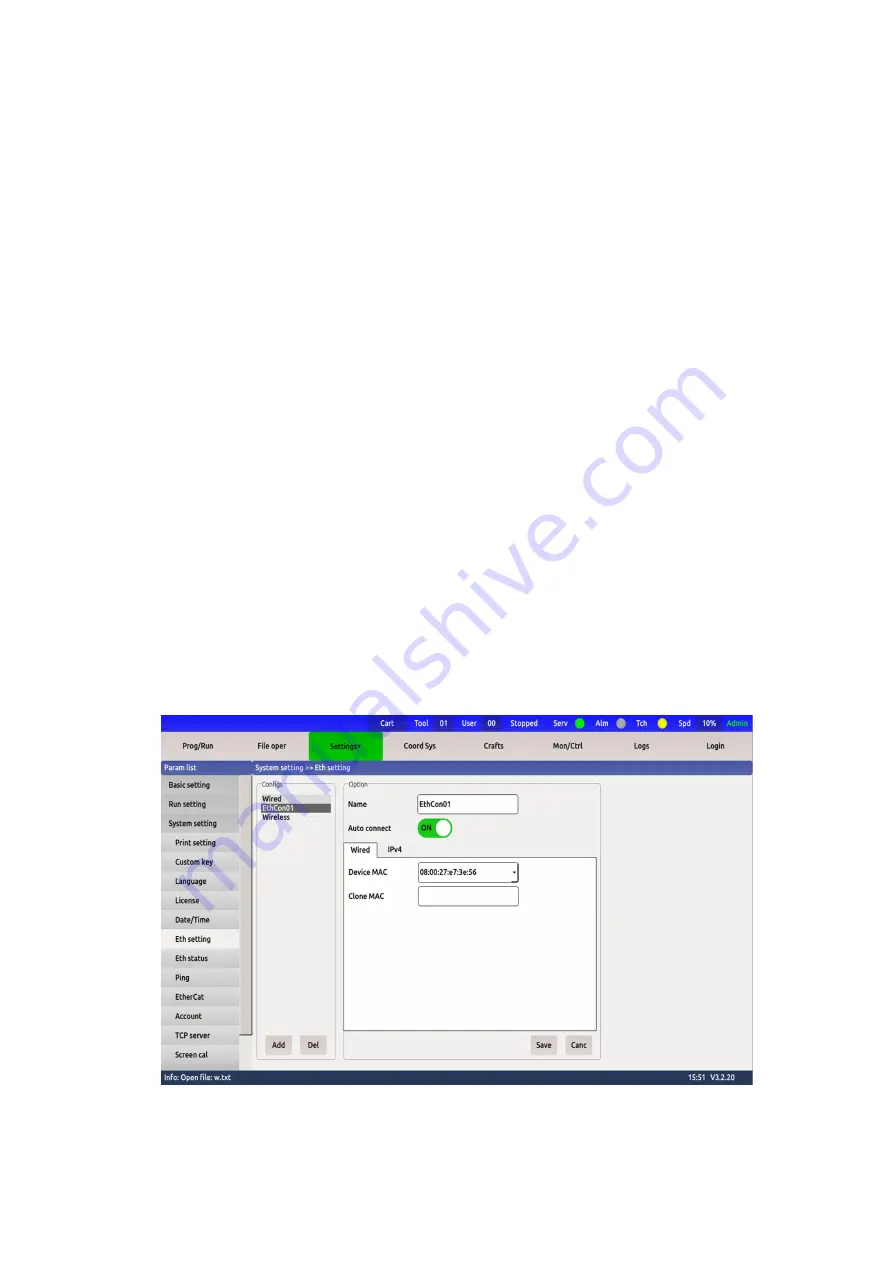
1) Robot operation interface configuration:
Setting path:
【
Parameter setting
】
->
【
System setting
】
->
【
Ethernet setting
】
->
【
Wired
】
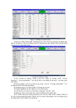
Just select Add below, and finally a list of connection names will appear. Choose the
name of the connection (the default is Wired connection 1). The interface is as follows:
Figure 4-10 Ethernet connection
For example, configure the robot's IP to 192.168.1.6. The set interface is as follows:


