background image

48- 

12


ANNEX A - Equipment specific process parameters 


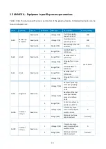
Table 15 lists the device-specific process parameters of the gripping module. A detailed description can be 

found in chapter 8.2.2. 


Index 

Function 

Access 

Subindex 

Data type 

Description 

Factory setting 

0x40 

Motion pa-
rameters 

Read/write 

UIntegerT(8) 

Override gripping 
speed in percent 

100 

Read/write 

UIntegerT(8) 

Override release 
speed in percent 

100 

Read/write 

BooleanT(8) 

Reverse reference run 
direction 

false 

0x60 

Grip 0 

Read/write 

IntegerT(16) 

NO PART LIMIT in 
1/100 mm 

see Table 12 

IntegerT(16) 

RELEASE LIMIT in 
1/100 mm 

UIntegerT(8) 

Gripping force in per-
cent 

0x61 

Grip 1 

Read/write 

IntegerT(16) 

NO PART LIMIT in 
1/100 mm 

IntegerT(16) 

RELEASE LIMIT in 
1/100 mm 

UIntegerT(8) 

Gripping force in per-
cent 

0xA0 

Diagnosis 

Read only 

UIntegerT(16) 

Duration of the last 
successful gripping 
process in millisec-
onds 

UIntegerT(16) 

Duration of the last 
successful release 
process in millisec-
onds 

IntegerT(16) 

Current module tem-
perature in 1/10 °C 

0x100 

Protocol 
Entry 0 

Read only 

UIntegerT(32) 

Time stamp meas-
ured in seconds from 
switch-on time 

StringT(140) 

Message text (max. 
140 characters) 

"(not set)" 


0x109 

Protocol 
Entry 9 

Read only 

UIntegerT(32) 

Time stamp meas-
ured in seconds from 
switch-on time 

StringT(140) 

Message text (max. 
140 characters) 

"(not set)" 

Summary of Contents for CLG Series

Page 1: ...1 Mounting and Operating Instructions CLG Series Electrical Gripping Modules with IO Link Hardware Version 1 September 2021...

Page 2: ...Qualification 8 2 5 Safety Considerations 8 2 6 Indications of Particular Hazards 8 3 Warranty 8 4 Scope of Delivery and Accessories 9 5 Technical Data 10 5 1 Nominal Mechanical Data 10 5 1 1 Permiss...

Page 3: ...of the Gripping Module 32 9 1 Gripping Commands 32 9 2 Position sensors 33 9 3 Reference Run 33 9 4 Gripping State 34 9 5 Parametrizable Grip Presets 35 9 5 1 Gripping Direction 36 9 6 Initialize grip...

Page 4: ...ation Example 50 13 1 Preparation 50 13 2 Configuration of the IO Link master 50 13 3 Configuration of the gripping module 53 13 4 Configuration of the Gripping Module 54 13 5 Diagnostics 55 13 6 Gene...

Page 5: ...ve gripping force control and integrated IO Link technology Figure 1shows the connectors and components of a CLG gripping module The gripping module can be configured either via the configuration soft...

Page 6: ...endanger the safety of per sonnel and plant damage the device or impair the function of the device Additional information for a better understanding of the described facts Reference to further inform...

Page 7: ...ng module is improperly mounted modified or incorrectly maintained the EC Machinery Directive the VDE guidelines the safety and accident prevention regulations appli cable at the place of use or the s...

Page 8: ...le Disconnect the power supply of the gripping module before any installation modification or adjust ment work 2 6 Indications of Particular Hazards Risk of injury from falling and ejected objects Pro...

Page 9: ...0071 Table 1 Part numbers scope of delivery The following accessories for the gripping module are available separately Flange adapter for robots with ISO standard flange Device configurator for grippi...

Page 10: ...L 1 mm 40 Permissible mass per finger g 60 Protection class IP 40 Ambient temperature C 5 50 Air humidity 0 90 non condensing Mechanical repeatability mm 0 03 Weight g 120 Table 2 Nominal mechanical...

Page 11: ...ts the finger speed depending on the parameterized gripping force according to Figure 3This minimizes gripping impulse and rebound effects during undamped gripping The central override parameter see c...

Page 12: ...anics 5 1 3 Cycle Times The following diagrams show the typical course of the gripping duration and the release duration for different gripping force settings The values shown indicate the typical dur...

Page 13: ...d forces and moments the load carrying capacity of the guide must be recalcu lated according to the following equation 0 1 0 C0 and T are the permissible guide loads according to Table 3 and M is the...

Page 14: ...technical sales department in advance Electrical operating data Unit CLG 30 006 Supply voltage V 18 30 Current consumption IDLE inactive mA 40 Current consumption HOLDING 25 force mA 40 Current consu...

Page 15: ...specified in the IO Link 1 1 standard It is therefore essential to check whether the IO Link master used can permanently supply the rated current specified in Table 4 1 3 2 4 Pin Strand colour Signal...

Page 16: ...ing holes that can be used to mount the gripping module can be found in the technical drawing The following maximum torques and minimum screw in depths must be ob served during assembly Thread M2 base...

Page 17: ...the accessory kit of the gripping module Figure 7 Mounting the fingers The recommended mounting materials are listed in Table 6 Position CLG 30 006 1 2 pcs Dowel pin ISO 2338 4h8 X 6 2 2 pcs Screw IS...

Page 18: ...n Up to two different parame ter sets can be configured via IO Link to reliably grip multiple workpieces A position window is defined for each workpiece in which the gripper must adjust itself If the...

Page 19: ...ay color as listed in Table 7 and Table 9 and the IO Link connection status is indicated by flashing or steady light of the display STATE Meaning green Ready for operation red Not ready Error LED flas...

Page 20: ...parameterization of the gripping module is stored This memory is volatile i e the configuration data stored will be lost when turning off or disconnecting the power supply The gripping module must th...

Page 21: ...X Table 9 Process data word IO Link master to gripping module RES Reserved data bits bit 15 11 These data bits are reserved and are currently not evaluated by the gripping module Their value should al...

Page 22: ...ster BYTE 0 31 30 29 28 27 26 25 24 POS BYTE 1 23 22 21 20 19 18 17 16 POS BYTE 2 15 14 13 12 11 10 9 8 RES PARTLOST RES BYTE 3 7 6 5 4 3 2 1 0 RES TEMPWARN TEMPFAULT FAULT HOLDING NO PART RELEASED ID...

Page 23: ...70 C can lead to malfunctions and permanent damage to the grip ping module FAULT Device error Bit 4 BooleanT If this bit is set the gripping module is in error state More detailed information on the...

Page 24: ...ic process data are not stored permanently in the gripping module They must be re configured on the gripping module with each restart For this purpose common IO Link masters offer the op tion of stori...

Page 25: ...peed in percent Reduces or increases the gripping speed automatically calculated from the specified gripping force The suitable gripping speed is automatically determined by the gripping module and is...

Page 26: ...ping module performs its reference run chapter 9 3 to the outside By setting this value to TRUE the direction of the reference run can be reversed to make the gripping module refer ence to the inside...

Page 27: ...ee Table 12 Example The nominal workpiece width when gripping from the outside is 7 mm the tolerance is selected as 2 mm Thus the NO PART LIMIT must be set to 5 mm which corresponds to a value of 500...

Page 28: ...nal gripping force Set the value to 100 Gripping with minimum gripping force 6 Set the value to 25 8 2 2 3 Diagnostic Parameters Duration of the last successful gripping operation Returns the duration...

Page 29: ...tocol memory comprises ten entries that can be read out via the device specific acyclic process pa rameters All entries are identical and are structured as follows The contents of the log memory are v...

Page 30: ...be sent directly via the con figuration software of the IO Link master The available commands are listed below Restart the gripping module code 0x80 This command can be used to restart the gripping mo...

Page 31: ...he heat dissipation from the gripping module should be checked Continued operation in case of a temperature error can lead to malfunctions and permanent damage to the gripping module 0x4210 Device Tem...

Page 32: ...in chapter 12 9 1 Gripping Commands The movement of the base jaws is controlled via the command bits of the cyclic process data The following commands are available ENABLE The gripping module is acti...

Page 33: ...the finger position is yet unknown when the gripping module is switched on The module must be referenced before it can execute movement commands During the refer ence run the gripping module moves th...

Page 34: ...osition with reduced force HOLDING HOLDING 1 Part is held The gripping module has been blocked between the RELEASE LIMIT and the NO PART LIMIT position and the base jaws do not move The workpiece is h...

Page 35: ...et is selected via the grip index value transferred in the cyclic process data and executed with the gripping com mands GRIP or RELEASE For parameterization a position window is specified for each gri...

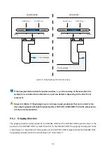
Page 36: ...nt Danger of collision If the gripping range is not large enough workpieces that are too small or too large may be gripped although the gripping state is NO PART or RELEASED If in doubt please evalu a...

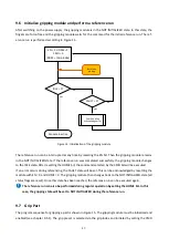
Page 37: ...completed successfully the gripping module changes to the IDLE state After resetting the HOME bit the command selected by the CMD bit will be executed If an error occurs during referencing the FAULT...

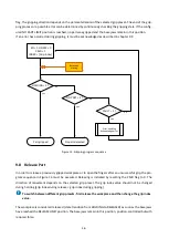
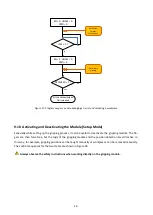
Page 38: ...error Figure 15 Gripping program sequence 9 8 Release Part In order to release a previously gripped workpiece or to open the fingers after an unsuccessful grip the pro gram sequence in Figure 16 must...

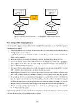
Page 39: ...onding system event is triggered that describes the cause of the error in more detail see Table 13 To acknowledge an error the gripping module must be disabled and then enabled again Figure 17 shows t...

Page 40: ...deactivate the gripping module The fin gers are then force free but the logic of the gripping module and the position detection are still active In this way for example gripping positions can be taugh...

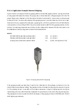
Page 41: ...workpiece is to be picked up by a gripping module positioned by a robot Choose a sufficiently large gripping range recommended distance between RELEASE LIMIT and NO PART LIMIT 2 mm to maximize the rel...

Page 42: ...s are set either via the configuration software of the IO Link master or via the GRIPLINK U1 device configurator available from Weiss Robotics GRIP 0 NO PART LIMIT Index 0x60 Subindex 0x01 120 1 20 mm...

Page 43: ...as GRIP 1 of the gripping module For this purpose the following parameters are set either via the configuration software of the IO Link master or via the GRIPLINK U1 device configurator available fro...

Page 44: ...RELEASE LIMIT value To release the workpiece execute the program sequence in Figure 16 Since GRIP 1 has been config ured in this example grip index 1 must also be used when executing the above progra...

Page 45: ...ctory Do not disassemble base jaws and belts The maintenance intervals must be adapted to the ambient and operating conditions The following factors must be taken into account Increased operating temp...

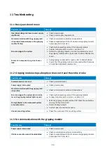
Page 46: ...application parameters 11 2 Gripping module stops abruptly or does not travel the entire stroke Possible cause Remedy Parameterization incorrect Check parameterization Power supply interrupted Check...

Page 47: ...tly Check environmental conditions Improve heat dissipation Shorten holding cycles or reduce gripping force Make sure that the base jaws are at a distance from the end stop in the RELEASED state Reduc...

Page 48: ...EASE LIMIT in 1 100 mm 3 UIntegerT 8 Gripping force in per cent 0x61 Grip 1 Read write 1 IntegerT 16 NO PART LIMIT in 1 100 mm 2 IntegerT 16 RELEASE LIMIT in 1 100 mm 3 UIntegerT 8 Gripping force in p...

Page 49: ...49 Table 15 Device specific process parameters...

Page 50: ...e PLC so that you can access the PLC via PROFINET Then configure the ET200eco PN IO Link master see Figure 21 The IO Link master maps the cyclic process data of the gripping module in the I O address...

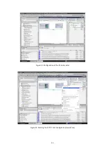
Page 51: ...51 Figure 21 Configuration of the IO Link master Figure 22 Starting the S7 PCT Port Configurator Device Tool...

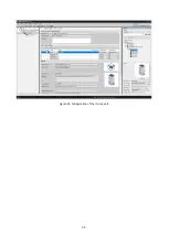
Page 52: ...52 Figure 23 Configuration of the IO Link port...

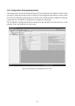
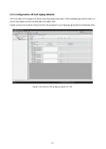
Page 53: ...tor establishes a connection to the IO Link master Selecting the gripping module in the tree view on the left loads the configuration of the grip ping module The Identification Parameters and Diagnost...

Page 54: ...e set gripping parameters of the available grip presets These val ues can be adjusted to the handling task to be performed System commands can be started via buttons for example to reset the gripping...

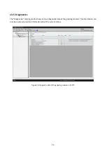
Page 55: ...Diagnostics tab Figure 26 shows various diagnostic data of the gripping module This information can only be read and provides information about the current status Figure 26 Diagnostic data of the gri...

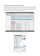
Page 56: ...ponding button is located in the Addresses tab in the configuration of the master Figure 27 The generated file can later be imported in the TIA Portal as an external source and converted into a data t...

Page 57: ...achine may not be put into operation until it is confirmed that the machine into which the incomplete machine is to be installed meets the provisions of the Machinery Directive 2006 42 EC Applied harm...

Page 58: ...ions in this document are subject to change without notice for product improvement Trademarks are the property of their respective owners Our products are not intended for use in life support systems...

Reviews: