SERIES AP440 ACROPACK
USER
’S MANUAL
Acromag, Inc. Tel: 248-295-0310
- 33 - http://www.acromag.com
- 33 -
www.acromag.com
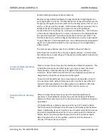
Event Sensing
The AP440 has edge-programmable event sense logic built-in for all 32 input
lines, IN00 through IN31. Event sensing may be configured to generate an
interrupt to the carrier, or to merely reflect the interrupt internally. Event
sensing is enabled in Enhanced Mode only and inputs can be set to detect
positive or negative events, on a nibble-by-nibble (group of 4 input lines)
basis. The event sensing is enabled on an individual channel basis. You can
combine event sensing with the built-in debounce control circuitry to obtain
“glitch-free” edge detection of incoming signals.
To program events, determine which input lines are to have events enabled
and which polarity is to be detected, high-to-low level transitions (negative)
or low-to-high level transitions (positive). Set each half-port (nibble) to the
desired polarity, and then enable each of the event inputs to be detected.
Optionally, if interrupt requests are desired, load the interrupt vector
register and enable the interrupt request line. Note that all event inputs are
reset, set to positive events, and disabled after a power-up or software reset
has occurred.
Change-Of-State Detection
Change-of-State signal detection requires that both a high-to-low and low-
to-high signal transition be detected. On the AP440, if change-of-state
detection for an input signal is desired, two channels connected to the same
input signal would be required--one sensing positive transitions, one sensing
negative transitions. Since channel polarity is programmable on a nibble
basis (group of four), the first nibble of a port could be configured for low-to-
high transitions, the second nibble for high-to-low transitions. As such, up to
16 change-of-state detectors may be configured.
Debounce Control
Debounce is available in Enhanced Mode only. With debounce, an incoming
signal must be stable for the entire debounce time before it is recognized as
a valid input or event at the FPGA input. Note that the debounce time
applies at the FPGA input and does not include the opto-coupler delay. You
can combine debounce with event sensing to obtain “glitch-free” edge
detection of incoming signals for all 32 channels. That is, the debounce
circuitry will help filter out “glitches” or transients that can occur on received
signals, for error-free edge detection and increased noise immunity.
The debounce circuitry uses the 31.25MHz carrier clock to derive the
debounce times. With the 31.25MHz carrier clock, a debounce value of 3-
4us, 48-64us, 0.75-1ms, or 6-8ms may be selected (see the Debounce
Duration Register). As such, an incoming FPGA signal must be stable for the
debounce time before it is recognized as a valid input or event.
Upon initialization of the debounce circuitry, be sure to delay by at least
three times the programmed debounce time before reading any of the input

