SERIES IP503 INDUSTRIAL I/O PACK EIA/TIA-232E & CENTRONICS COMMUNICATION MODULE
___________________________________________________________________________________________
- 18 -
The most common asynchronous serial data format is 1 start
bit,8 data bits, and 1 stop bit, with no parity. The following table
summarizes the available data formats:
START BIT
Binary 0 (a shift from “Mark” to “Space”)
DATA BITS
5,6,7, or 8 Bits
PARITY
Odd, Even, or None
STOP BIT
Binary 1 (1, 1-1/2, or 2 Bit times)
With start, stop, and parity in mind, for an asynchronous data
byte, at least one bit will be a 1 (the stop bit)This defines the
break signal (all 0 bits with a 1 stop bit lasting longer than one
character)A break signal is a transfer from “mark” to “space” that
lasts longer than the time it takes to transfer one character.
Because the break signal doesn’t contain any logical 1’s, it
cannot be mistaken for data. Typically, whenever a break signal
is detected, the receiver will interpret whatever follows as a
command rather than data. The break signal is used whenever
normal signal processing must be interrupted. In the case of a
modem, it will usually precede a modem control command. Do
not confuse the break signal with the ASCII Null character (00),
since a break signal is longer than one character time. That is, it
is any “space” condition on the line that lasts longer than a single
character (including its framing bits) and is usually 1-1/2 to 2
character times long
The baud rate is a unit of transmission speed equal to the
number of electrical signals (signal level changes) sent on a line
in one second. It is thus, the electrical signaling rate or frequency
at which electrical impulses are transmitted on a communication
line The baud rate is commonly confused with the bit transfer rate
(bits-per-second), but baud rate does not equate to the number of
bits transmitted per second unless one bit is sent per electrical
signal. That is, one electrical signal (change in signal level) may
contain more than one bit (as is the case with most phone
modems)While bits-per-second (bps) refers to the actual number
of bits transmitted in one second, the baud rate refers to the
number of signal level changes that may occur in one second.
Thus, 2400 baud does not equal 2400 bits per second unless 1
bit is sent per electrical signal. Likewise, a 1200bps or 2400bps
modem operates at a signaling rate of only 600 baud since they
encode 2 and 4 bits, respectively, in one electrical impulse
(through amplitude, phase, and frequency modulation
techniques)However, for this device, the baud rate is considered
equivalent to the bit rate
This module supports the common EIA/TIA-232E DB9
interface definition which is a subset of the full EIA/TIA-232E
standard. This subset includes support of Data Carrier Detect
(DCD), Data Set Ready (DSR), Receive Data Line (RxD),
Request to Send (RTS), Transmit Data Line (TxD), Clear to Send
(CTS), Data Terminal Ready (DTR), and Ring Indication (RI), plus
signal ground. A complete DB9 DTE port would require 3
transmitters and 5 receivers, a complete DB9 DCE port would
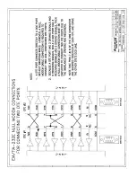
require 5 transmitters and 3 receivers. A DTE port will connect
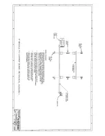
directly to a DCE port without swapping wires. However, a null-
modem cable connection is required to connect two like-
configured DTE ports due to the imbalance of drivers and
receivers (see Drawing 4501-572)
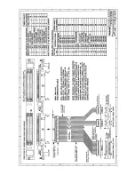
Pins 1-18 of field I/O connector P2 provide connectivity to
serial ports A & B of this module (refer to Table 21 for pin
assignments)Note that a suffix of ‘_A’ or ‘_B’ is appended to the
signal names to indicate whether it is for port A or port B
Each of these signals are described in detail below assuming that
a local DTE device (PC) is connected to a local DCE device
(modem) communicating over a telephone line to a remote DCE
device (remote modem) connected to a remote DTE (another PC)
EIA/TIA-232E Signal Descriptions
(An Asterisk (*) is used to indicate an active-low signal)
SIGNAL
DESCRIPTION
DCD_A*
DCD_B*
Data Carrier Detect (DCE-to-DTE) - This signal is
driven by the DCE to inform the DTE that it is
receiving a carrier signal. If it is held off locally,
then it tells the local DTE that the remote DTE has
not switched its RTS circuit on yet and the local
DTE can gain control over the line if needed. If
held on locally, then it tells the local DTE that the
remote modem has received an RTS on condition
from its remote DTE and the remote DTE is in
control over the carrier line
DSR_A*
DSR_B*
Data Set Ready (DCE-to-DTE) - This signal is
driven by the DCE to indicate to the DTE that it is
connected to the line. Both modems turn DSR on
to indicate that a communication path has been
established between the local and remote modems
RxD_A
RxD_B
Receive Data Line (DCE-to-DTE) - This is the
receive data line from the modem to the DTE. The
signals on this line are in serial form. When DCD
is held off, this line is held in the mark state
TxD_A
TxD_B
Transmit Data Line (DTE-to-DCE) - This is the
transmit data line from the DTE to the modem.
When no data is being sent, this signal line is held
in the mark state. For data to be transmitted, DSR,
DTR, RTS, and CTS must all be in the on state
(asserted)
RTS_A*
RTS_B*
Request-to-Send (DTE-to-DCE) - RTS is turned on
by the DTE to tell the DCE it is ready to transmit
data. This is also passed to the remote DCE. The
DCE will turn CTS on in response to tell the DTE it
is ready to receive data. As such, RTS. acts to
control the direction of data transmission. It is
turned ON in transmit mode and turned OFF when
transmission is completed or in receive mode (the
DCE will turn CTS off in response)
DTR_A*
DTR_B*
Data Terminal Ready (DTE-to-DCE) - DTR is used
in conjunction with DSR to indicate equipment
readiness. DTR is turned on by the DTE to tell the
DCE it is ready to receive or transmit data. DTR
must be on before the DCE can turn DSR on. By
keeping DTR on, the DTE lets an auto-answer
modem accept a call unattended. When DTR is
turned off, the DCE is removed from the
communication channel following completion of
transmission and blocked from accepting calls from
the remote DCE
CTS_A*
CTS_B*
Clear-to-Send (DCE-to-DTE) - CTS is turned on by
the DCE to indicate it is ready to receive data from
the DTE and the local modem has control over the
telephone line. CTS is turned on in response to
simultaneous on conditions of the RTS, DSR, and
DTR signals
RI_A*
RI_B*
Ring Indicator (DCE-to-DTE) - When the modem
receives a call (auto-answer), the DCE switches RI
on and off in sequence with the phone ringer to tell
the DTE that a call is present and a remote modem
is requesting a dial-up connection

