17
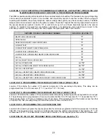
LOCATION 145-148: PROGRAMMING THE AUXILIARY OUTPUTS
Four of the functions in the following table are available on terminals 1 thru 4. These outputs are often used to switch
small relays, LED's, trip long range radio, or to add a remote sensor. For example, to create an LED that
lights for alarm memory, program a "7" into location 145. Wire the positive lead of the LED to terminal 26 (positive aux
power) and the negative lead through a limiting resistor of approximately 650 ohms to PIN #1 (top pin) of the aux
output pin connector. If the LED operation is "ON" when you want it to be "OFF", see location 149.
NOTE: NO MORE
THAN 20 MILLIAMPS CAN BE SUPPLIED FROM THESE TERMINALS.
DATA
ACTIVATION ON
NOTES
"0"
ARMED STATE
LATCHED OUTPUT
"1"
READY
LATCHED OUTPUT
"2"
BURG/PANIC SIREN
RECYCLED OUTPUT
"3"
PRIORITY SIREN
RECYCLED OUTPUT
"4"
ARMED WITH BYPASS
LATCHED OUTPUT
"5"
AC POWER
LATCHED OUTPUT
"6"
LOW BATTERY
LATCHED OUTPUT
"7"
ALARM MEMORY
LATCHED OUTPUT
"8"
ENTRY
LATCHED OUTPUT
"9"
EXIT
MOMENTARY OUTPUT
LOCATIONS 149: INVERTING THE AUXILIARY OUTPUTS
Auxiliary outputs are normally "OFF", and turn "ON" when the selected condition occurs. For outputs you wish to
reverse, add up their values according to the chart below and program the sum in this location. For example, to
reverse outputs 2 and 3, program a "6" (2 + 4 = "6") in location 149.
VALUE
DESCRIPTION
1
Invert auxiliary 1 output
2
Invert auxiliary 2 output
4
Invert auxiliary 3 output
8
Invert auxiliary 4 output
LOCATION 150: AC POWER LOSS DELAY FEATURE
Location 150 is used to disable the 5 minute delay before reporting an AC power failure. If a "1" is programmed in this
location, AC power failures will be reported immediately. If a "0" is programmed in this location, AC power failures will
not be reported until the power has been off for 5 minutes.


