•
•
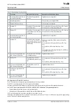
Table 23: Commissioning Test using Libraries
Test steps
Reason for the test step
Expected result for Danfoss library
1
Run the application (all the ser-
vo drives are enabled).
Check that the application
can run.
Application runs as expected.
2
Stop the application.
–
All servo drives are at speed 0 RPM.
3
Disable all the servo drives.
–
All servo drives are disabled.
4
Enable STO.
Check that STO can be activa-
ted without error.
MC_ReadAxisInfo_DDS
output
SafeTorqueOff
= True for
all servo drives on the corresponding line.
5
Disable STO.
Check that STO can be deacti-
vated without error. No reset
is required.
MC_ReadAxisInfo_DDS
output
SafeTorqueOff
= False for
all servo drives on the corresponding line.
6
Run the application (all the ser-
vo drives are enabled).
–
Application runs as expected.
7
Enable STO.
Check that errors are gener-
ated correctly when STO is ac-
tivated while the servo drives
are running.
Motors are torque free. Motors coast and stop after
some time.
MC_ReadAxisInfo_DDS
output
SafeTorqueOff
= True
and
MC_ReadStatus_DDS
output
ErrorStop
= True
and
MC_ReadAxisError_DDS
output
AxisErrorID
= 0xFF80 on
all enabled servo drives.
8
Try to run the application (ena-
ble 1 or more servo drives).
Checks that the STO function
is working correctly.
Application does not run.
9
Disable STO.
Check that the STO start is
still inhibited by the error sig-
nal.
MC_ReadAxisInfo_DDS
output
SafeTorqueOff
= False
and
MC_ReadStatus_DDS
output
ErrorStop
= True
10 Try to run the application (ena-
ble 1 or more servo drives).
Check whether reset is re-
quired.
Application does not run.
11 Send a reset signal via
MC_Re-
set(_DDS)
.
–
MC_ReadAxisInfo_DDS
output
SafeTorqueOff
= False
and
MC_ReadStatus_DDS
output
ErrorStop
= False
12 Try to run the application (all
servo drives are enabled).
–
Application runs as expected.
8.9 Operation of the STO Function
The STO function does not require any parameterization and is always enabled.
The ISD 511 servo drive provides STO status signals via the fieldbus.
All signals transmitted via the fieldbus are not part of the safety function and can only be used for operational purposes.
See the
VLT® Servo Drive System ISD 510, DSD 510, MSD 510 (VLT® Flexmotion
™
) Programming Guide
for:
General information on how to access and map data objects.
Information on a library provided to simplify the use of the fieldbus functions.
If STO is activated when the servo drive is enabled, an error code is issued.
If the drive is not enabled and STO is activated, it is not necessary to reset any STO error. It is sufficient to re-apply the supply voltage
to the STO terminals, before enabling the drive.
AQ377148425069en-000101
/ 130R1213 | 93
Danfoss A/S © 2023.08
Safety Concept
VLT® Servo Drive System ISD 511
Operating Guide

