VersaGateway User’s Manual
Document #: 2015006.1.pdf
PAGE 13 of 44
Divelbiss Corporation • 9778 Mt. Gilead Road • Fredericktown, Ohio 43019 • 1-800-245-2327 • www.divelbiss.com
Device Features
Status LED Indicators
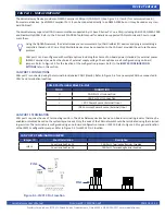
The VersaGateway Device provides two pre-defined on-board LED indicators. Refer to Figure 1-5 for general locations of the LED
indicators. The two indicators are: PWR and STS.
PRE-DEFINED LED INDICATORS
LED NAME
DESCRIPTION
PWR
Power OK (green). On when proper input power is detected.
STS
Status/Watchdog (green). Flickers when no KERNEL is installed. Flashes
slowly when KERNEL is installed, but no ladder diagram is running. Flashes
about 4x per second when a ladder program is executing.
Programmable LED Indicators
PROGRAMMABLE LED INDICATORS
LED NAME
DESCRIPTION
I1
Indicator 1 (green). General Use based on I1 boolean variable in ladder dia
-
gram program.
I2
Indicator 2(green). General Use based on I2 boolean variable in ladder dia
-
gram program.
I3
Indicator 3 (green). General Use based on I3 boolean variable in ladder dia
-
gram program.
I4
Indicator 4 (green). General Use based on I4 boolean variable in ladder dia
-
gram program.
I5
Indicator 5 (green). General Use based on I5 boolean variable in ladder
diagram program. With I5 being red in color, it is ideal to be used as a fault
indicator if a fault indication would be required.
There are five (5) user programmable LED indicators (4 Green, 1 Red) on the VersaGateway. These LED indicators are available for
use in the ladder diagram program for any purpose. Refer to Figure 1-5 for the LED indicator locations.
When the VersaGateway is selected as the target in EZ LADDER Toolkit, the programmable user LED indicators are automatically
added and boolean variables are automatically created. These variables may be added to the ladder diagram project workspace as
needed as boolean variables or coils and be connected to functions and function blocks. The variables for the programmable user
LED indicators are named I1, I2, I3, I4 and I5; the same as their controller board designation. Refer to the P-Series EZ LADDER Toolkit
manual for details using contacts, coils and boolean variables in ladder diagrams.
CAN Port 0
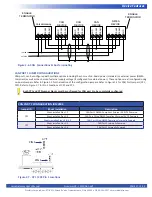
The VersaGateway Device provides a standard configuration CAN port (CAN port 0) for communications to / from external devices.
The VersaGateway supports all CAN communications supported by it’s base P-Series PLC on a Chip, including SAE J1939, NMEA 2000
and Divelbiss OptiCAN. Refer to the P-Series EZ LADDER Toolkit manual for details on supported CAN protocols and how to imple
-
ment them.
Using the OptiCAN network, the VersaGateway can communicate to other Divelbiss I/O devices and programmable logic
controllers (based on PLC on a Chip). Multiple devices may be connected to the CAN port provided they all use the same
protocol.


