24
User Manual
MN032006EN
Effective December 2017
415U Condor-long-range
wireless I/O and gateway
EATON
www.eaton.com
Force Mapping
Transmit Register
Allows you to configure an I/O location that will force the mapping to be sent when the I/O location is written
to. External devices, such as Modbus Master/Clients, can initiate the transmission of a mapping by writing to an
internal register that then forces the transmission to occur. For more information and examples, see “Startup or
force configuration”.
Note
: Digital inputs 1–8 cannot be used as a force trigger because the digital inputs are continually being
scanned by the internal processor and each time a scan occurs it would force the mapping to be sent. If a digital
input is required to be used as the trigger, map the digital input to a general purpose bit storage register (501,
10501, and so on), and then use this general purpose register to trigger the force mapping.
Startup or force configuration
When a module is first powered on, it transmits update messages
to remote modules based on how the input mappings are
configured. The module’s outputs will remain in the default “off”
condition until the module receives an update or change-of-state
message from the remote modules—unless a fail-safe block has
been configured for the output, in which case it will default to the
value configured in the fail-safe block. For more information, see
“Fail-safe blocks” on
page 30
.
To ensure that the module outputs are updated with the latest
remote input status when the module is first powered on, you can
configure the module to transmit a special startup or force message
that will write a value into an internal register at the remote module
(or modules). The remote module can then use this register to force
any mappings that it has configured for the destination. To configure
a force register, see the previous section, “Adding or editing mapping
parameters” on
page 22
.
When the force register is activated, any mapping configured with
this force register will immediately send an update message to
the destination so that its outputs can be set to the latest value. It
may be necessary to configure a startup or force message for each
remote module that sends values back to the module’s outputs.
Example
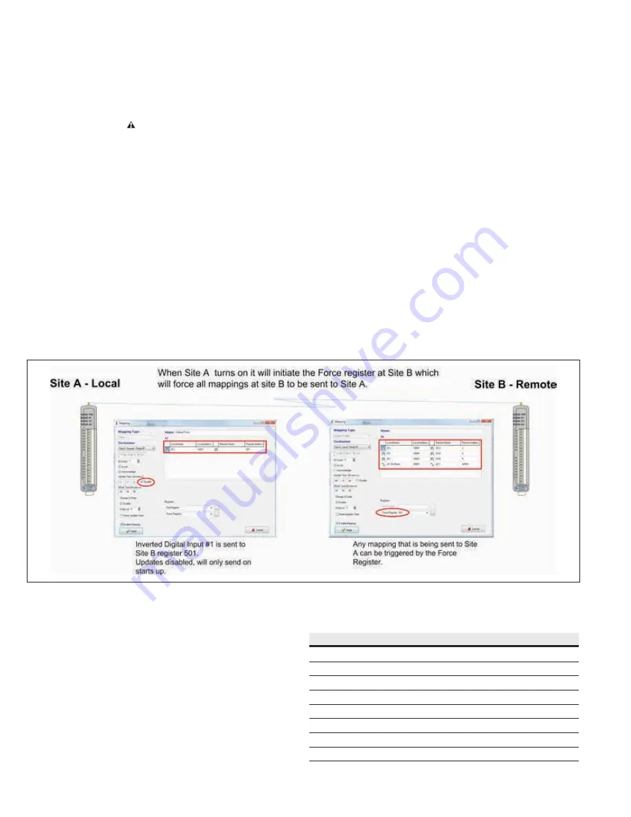
In the example shown in
Figure 38
, site A needs to be configured
so that on power-up it writes to a register at Site B. Site B then
uses this register to trigger an update of any mappings it has that
communicate back to Site A. If the system has multiple remote
sites that require startup or force configuration, Site A needs to
have configured a startup or force mapping for each remote site. If
there were multiple remotes in this example, all mappings from the
remote sites that are sent to Site A would use the force register
configured for 501.
Figure 38. Startup or force configuration
Address map
The I/O data store provides storage for all I/O data, both local data
and data received from the system. The I/O store provides four
register types—two bit registers, two word registers, two long-word
registers, and two floating point registers. In addition, each register
type supports both inputs and outputs, making a total of eight
register address ranges that are used for physical I/O and gateway
storage. These files
are mapped into the address range as described
in the following table. The addressing uses standard Modbus
protocol formatting and is also common to the ELPRO protocol.
Table 4. Address map
Type
Size
Address
Discrete outputs
6000 (bits)
00001
Discrete inputs
6000 (bits)
10001
Word (unsigned) inputs (16-bit)
6000 (words)
30001
Word (unsigned) outputs (16-bit)
6000 (words)
40001
Long inputs (32-bit)
20 (longwords)
36001
Float inputs (32-bit)
20 (floats)
38001
Long outputs (32-bit)
20 (longwords)
46001
Float outputs (32-bit)
20 (floats)
48001


