30
User Manual
MN032006EN
Effective December 2017
415U Condor-long-range
wireless I/O and gateway
EATON
www.eaton.com
Adding expansion I/O modules
You can connect additional 115S serial expansion I/O modules to the
415U module if more I/O is required. The RS-485 serial port on the
415U is configured by default to communicate with 115S expansion
modules using the Modbus protocol. The default serial parameters
of the RS-485 port on the 415U are 9600 baud, no parity, 8 data
bits, 1 stop bit, which match the default settings of the 115S serial
expansion modules. You can change these parameters to increase
poll speeds in larger systems, but the serial module’s parameters
must match that of the 415U RS-485 port.
If more than three serial expansion I/O modules are added to the
415U module, you will need to adjust the Maximum Connections
setting for RS-485 or RS-232. To display these configuration screens,
select the module in the project tree and click
RS
-
485
or
RS
-
232
.
Note
: Reducing the Maximum Connections setting will slightly
improve the serial scan time. However, you need to make sure that
the slave addresses fall within the Maximum Connections. If the
Slave address is above the Maximum Connections, it will not be
polled.
When you connect the serial expansion module, before powering
on, set the expansion module address using the rotary switches on
the bottom of the module. Assign addresses sequentially, starting
at address 1. Make a note of the module address. This address will
be used as an offset to locate the I/O within the 415U-2. Also make
sure that the termination switch is “on” (down) for the last module in
the RS-485 loop.
Note
: Failure to terminate the RS-485 correctly will result in
modules not operating correctly.
115S Expansion I/O Memory map
The I/O data on the 115S module is read into memory locations
according to their Modbus address. The maximum supported
Modbus address is 19. Each 115S module has an offset that applies
to the location of its registers. This offset is equal to the units
Modbus address (selected on the rotary switch on the end of the
115S expansion I/O module), multiplied by 20.
If the modules Modbus address is 15, the offset value will be
15 X 20 = 300.
For example, if connecting a 115S-11 (16 x DIO) with address #15:
•
Digital input 1 will be at register location 10301
•
Digital Output 1 will be at register location 301
If using a 115S-12 (8 x DIO and 8 AIN) with address 16:
•
Digital input 1 will be at register location 10321
•
Analog input 1 will be at register location 30321
For a detailed address map of the serial expansion I/O modules,
see
page 73
.
When adding expansion I/O modules to the 415U-2, there are
two inbuilt registers indicating the communication status of the
expansion I/O module:
•
Communication fail
—Located at register location 10019 + offset
value. This register indicates “1”when the module is in failure.
•
Communication oK
—Located at register location 10020 +
offset value. This register indicates “1”when the module is
communicating properly.
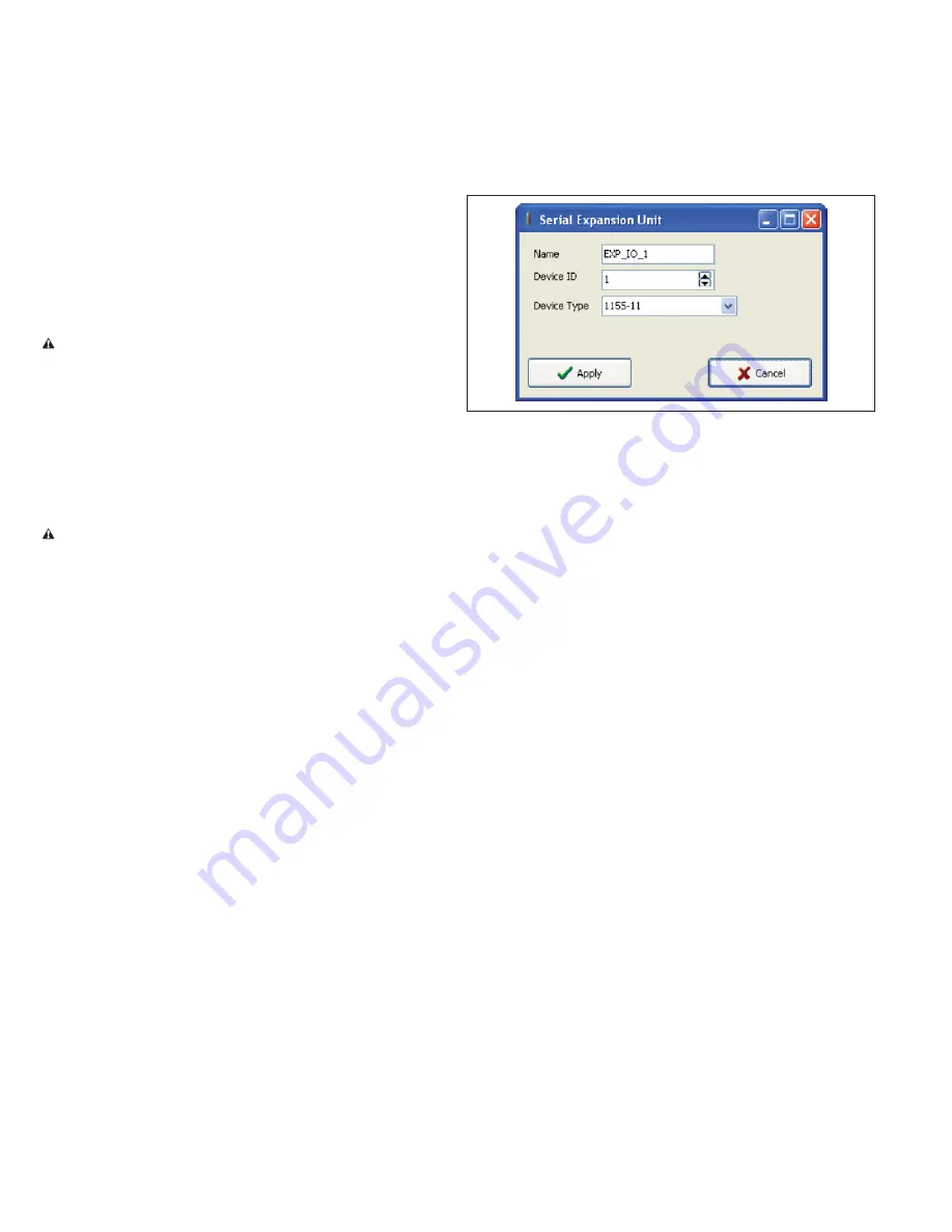
Adding an expansion I/O to in CConfig
In CConfig to add a 115S expansion I/O to the CConfig utility, open
the module in the project tree and click
Expansion
, and then click
Add
(see
Figure 47
).
Figure 47. Serial expansion unit
Name
Enter a name for the 115S expansion I/O module,
or leave the default name. The name can be up to
30 characters, including spaces.
Device ID
Select the address of the expansion I/O module. The
address is found on the rotary switch on the bottom
of the 115S expansion I/O module.
Device type
Select the module type from the drop down list.
Fail-safe blocks
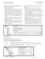
To configure fail-safe blocks for a module, open the module in
the project tree and click
Fail-safe Blocks
. The Fail-safe Block
configuration screen (
Figure 55
) allows you to set registers to a
pre-configured value on startup and configure the outputs to reset
to a predefined value after a timeout period has elapsed. When the
actual value is received, the register is automatically updated with
this value. If the value is lost because of a communication problem,
the register can be configured to set the register to a fail-safe value
after the pre-configured time. You can have a maximum of 50 fail-
safe blocks.
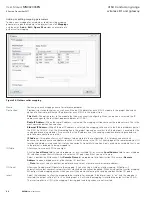
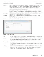
In the example shown in
Figure 48
, register 40501 holds an analog
value that has been mapped from another module and is updated
every 60 seconds. The fail-safe block is configured so that on
startup the module will write a value of 16384 into register 40501,
and then start counting down the fail timeout period (in this case,
600 seconds), which is a little over two times the update period
from the sending module. If the module has not received an update
from the other module after 600 seconds, register 40501 will be
set to the fail value (in this case, Invalid). If the “Invalidate” option
is selected, the value will be set to a null or invalidated value (~). If
this register happens to be mapped to another module and the state
is “Invalid,” the mapping will be inhibited until the invalid value is
updated with an actual value.

