APPENDIX A ASSEMBLER (Sub tool chain)
S5U1C88000C MANUAL II
EPSON
211
WORKBENCH/DEV TOOLS/OLD ASSEMBLER
<Control of program and data memory>
This section will explain how to control the memory of the program and data.
The S1C88XXX memory map can be categorized in the program memory (ROM) for the program code
and RAM and I/O memory for the data.
For example, even if a certain symbol is noted in a voluntary position in the assembly source file, the
asm88 is not capable of determining whether this is within the program memory or data memory.
For this reason, there is a need to clarify which memory each line comes under by prior instruction
through the section setting pseudo-instructions.
The following explains the section set methods for the relocatable assembly, and the asm88 process
corresponding to the method.
Setting sections
The absolute address allocated within each module of the relocatable assembly will be specified or
determined upon liking. Therefore, an absolute address cannot be specified within the assembly
source file. A relative address specification can be made using an ORG pseudo-instruction, however,
in this case, a standard for a relative address will be required. What's more, there is also a need to
specify the segments of the program and data area for the asm88.
The entire program for this assembler is categorized into CODE and DATA. These basically indicate
the following areas.
CODE section:
Program data area written in the ROM
DATA section:
Data memory area other than ROM
The asm88 is complete with a CODE and DATA pseudo-instruction to specify the section. The area
can be set through descriptions in the assembly source file.
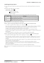
Specifying the CODE section
If a CODE pseudo-instruction is described within an assembly source file, the asm88 will assemble it
to be allocated to the CODE section until the next DATA pseudo-instruction appears. The CODE
pseudo-instruction can be used in several places within one module. The asm88 assumes the head of
the CODE section within the module as relative address 0000H and will continuously realign them in
the order that the CODE pseudo-instruction appears to consolidate it into one block. In other words, a
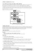
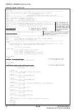
CODE specification range of one module will be handled as one CODE section. (Refer to Figure
A.2.3.2.1.)
The CODE section of each module is further consolidated as a whole by the linker. The linker will link
in sectional units in accordance with the bank control within the program memory area.
The CODE section consists of CODE sections with one or multiple modules and the maximum size is
limited to 32K bytes as one bank is. (Details on section control will be explained in "A.2.4.2 Section
control".) Therefore, the programmer must be careful not to use more than 32K bytes in the code when
creating a module. The capacity of the CODE section can be verified by using the -ROM# flag when
starting-up the asm88. Use of this feature is advised. For example, when flag specification for "-ROM
32768" is performed, an error message will be displayed if a CODE section of one module exceeds 32K
bytes.
Specifying the DATA section
If a DATA pseudo-instruction is described within an assembly source file, the asm88 will assemble it
to be allocated to the DATA section until the next CODE pseudo-instruction appears. The DATA
pseudo-instruction can be used in several places within one module. The asm88 assumes the head of
the DATA section within the module as relative address 0000H and will continuously realign them in
the order that the DATA pseudo-instruction appears to consolidate it into one block. In other words, a
DATA specification range of one module will be handled as one DATA section. (Refer to Figure
A.2.3.2.1.)
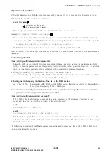
The DATA section of each module is further consolidated as a whole by the linker. The linker will link
in sectional units in accordance with the page control within the data memory area.


