CNC 8055
CNC 8055i
·M· & ·EN· M
ODELS
S
OFT
: V02.2
X
10
·205·
MULTIPLE MACHINING
Multiple machining is defined as a series of functions which allow a machining operation to be
repeated along a given path.
The programmer will select the type of machining, which can be a canned cycle or a subroutine
(which must be programmed as a modal subroutine) defined by the user.
Machining paths are defined by the following functions:
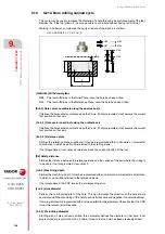
G60: Multiple machining in a straight line.
G61: Multiple machining in rectangular pattern.
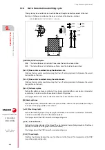
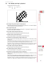
G62: Multiple machining in a grid pattern.
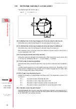
G63: Multiple machining in a circular pattern.
G64: Multiple machining in an arc.
G65: Machining programmed with an arc-chord.
These functions can be performed on any work plane and must be defined every time they are used,
as they are not modal.
It is absolutely essential for the machining which it is required to repeat to be active. In other words,
these functions will only make sense if they are under the influence of a canned cycle or under the
influence of a modal subroutine.
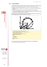
To perform multiple machining, follow these steps:
1.
Move the tool to the first point of the multiple machining operation.
2.
Define the canned cycle or modal subroutine to be repeated at all the points.
3.
Define the multiple operation to be performed.
All machining operations programmed with these functions will be done under the same working
conditions (T,D,F,S) which were selected when defining the canned cycle or modal subroutine.
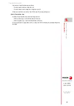
Once the multiple machining operation has been performed, the program will recover the history
it had before starting this machining, even when the canned cycle or modal subroutine will remain
active. Now feedrate F corresponds to the feedrate programmed for the canned cycle or modal
subroutine.
Likewise, the tool will be positioned at the last point where the programmed machining operation
was done.
If multiple machining of a modal subroutine is performed in the Single Block mode, this subroutine
will be performed complete (not block by block) after each programmed movement.
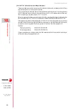
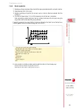
A detailed explanation is given on the next page of multiple machining operations, assuming in each
case, that the work plane is formed by X and Y axes.
Summary of Contents for 8055 EN
Page 1: ...CNC 8055 M EN Programming manual Ref 1711 Soft V02 2x...
Page 8: ...8 Programming manual CNC 8055 CNC 8055i SOFT V02 2X...
Page 12: ...12 CNC 8055 CNC 8055i Declaration of conformity and Warranty conditions...
Page 16: ...16 CNC 8055 CNC 8055i Version history...
Page 22: ...22 CNC 8055 CNC 8055i Returning conditions...
Page 24: ...24 CNC 8055 CNC 8055i Additional notes...
Page 26: ...26 CNC 8055 CNC 8055i Fagor documentation...
Page 448: ......
Page 464: ...464 Programming manual CNC 8055 CNC 8055i D M EN MODELS SOFT V02 2X Key code...
Page 466: ...466 Programming manual CNC 8055 CNC 8055i D M EN MODELS SOFT V02 2X Key code MC operator panel...
Page 467: ...Programming manual CNC 8055 CNC 8055i D M EN MODELS SOFT V02 2X 467 Key code...
Page 468: ...468 Programming manual CNC 8055 CNC 8055i D M EN MODELS SOFT V02 2X Key code...
Page 471: ...Programming manual CNC 8055 CNC 8055i D M EN MODELS SOFT V02 2X 471 Key code 11 LCD Monitor...
Page 472: ...472 Programming manual CNC 8055 CNC 8055i D M EN MODELS SOFT V02 2X Key code...
Page 478: ...478 Programming manual CNC 8055 CNC 8055i F M EN MODELS SOFT V02 2X Maintenance...
Page 479: ...Programming manual CNC 8055 CNC 8055i F SOFT V02 2X 479...
Page 480: ...480 Programming manual CNC 8055 CNC 8055i F SOFT V02 2X...
Page 481: ......

