Chapter 2 Features
2-5
The rule of the IO number of remote stations in H series is shown.
Data Type
Numbering rule
In case of EH-RMD
Bit data
X
Y
Bit number is 0 to 15, because “Y16”
and ”X16” are used.
Word data
WX
WY
Word number is fixed 0, because “Y16”
and ”X16” are used.
Double word data
DX
DY
Word number is fixed 0, because “Y16”
and ”X16” are used.
The following composition is explained to an example in detail.
Node 1: Input 2Byte (RDX16D)
Node 2: Output 2Byte (RDY16T)
Node 3: Input 8Byte, Output 8Byte (L100DN)
Node 4: Output 2Byte (RDY16R)
The I/O mapping by configurator is as follows.
Offset
Address
Output Data
Offset
Address
Input Data
0 02,
RDY16T
0 01,
RDX16D
1
03, L100DN (1
st
word)
1
03, L100DN (1
st
word)
2
03, L100DN (2
nd
word)
2
03, L100DN (2
nd
word)
3
03, L100DN (3
rd
word)
3
03, L100DN (3
rd
word)
4
03, L100DN (4
th
word)
4
03, L100DN (4
th
word)
5 04,
RDY16R
5
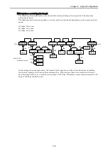
If reading real IO assign is performed from Ladder Editor for Windows® after mapping IO data on DeviceNet by configurator,
it can read as shown in the following figure.
Bit number (00 to 95) in the module
Slot number (0-F)
Station number (0-9)
Remote Master number (1-4)
RD Y1 6 T
L 1 0 0 D N
RD Y1 6 R
RD Y1 6 T
L 1 0 0 D N
Word number (0 to 7) in the module
Slot number (0-F)
Station number (0-9)
Remote Master number (1-4)
Word number (0 to 7) in the module
Slot number (0-F)
Station number (0-9)
Remote Master number (1-4)


