background image

Chapter 5    Master Module Specifications 

5-21 


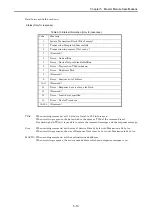
Control flag details 


+0  [0] Send data flag 


+1  [1] Initializing flag 


[0] Send data flag : 

Set 1 by user program to send explicit message. This flag
is cleared after communication completed.   
 

[1] Initializing flag : 

 Set 1 by user program to initialize the FUN 

command or to clear timeout. Received message is 
cleared as well.   


Sending area details 


+0 

Size 


+1 

Service 

MACID 


+2 

Class 


+3 

Instance 


+4  Service data 1 

Service data 0 


Max. 64 byte for service data 


  Service data 63 

Service data 62 


Sending error code 


  Error code 


Size : 
    Service data (sending area from s+4 to s+n) size with 
    byte unit


*) If the byte size is odd number, the last byte is stored in   
        lower byte. 


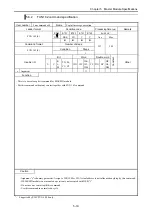
Error code 

Name 

Remarks 

0001H Timeout 

error  Detected 

by EH-RMD (timeout 3 sec.)   

0002H 

Data size error 

Detected by EH-RMD 

0003H 

Mail box error 

Detected by EH-RMD 

0101H Timeout 

error  Detected 

by CPU (timeout 5 sec.) 

0202H 

Range error 

Data size exceeds configured sending area. 

0203H 

Slot number error 

Slot number must be 0 to 7. 

0204H 

No module error 

EH-RMD is not mounted on configured slot. 


Summary of Contents for HIDIC EH-150

Page 1: ...HITACHI PROGRAMABLE CONTROLLER DeviceNet Master Module EH RMD Slave Controller EH IOCD Discrete I O slave unit RDX16D RDY16TP RDY16R APPLICATION MANUAL NJI 364A X ...

Page 2: ...red If you have any questions regarding the warranty please contact either your supplier or the local Hitachi Distributor Depending on failure part examination might be impossible Ordering parts or asking questions When contacting us for repair ordering parts or inquiring about other items please have the following details ready before contacting the place of purchase 1 Model 2 Manufacturing numbe...

Page 3: ...he circumstances items marked with may result in major accidents In any case they both contain important information so please follow them closely Icons for prohibited items and required items are shown below Indicates prohibited items items that may not be performed For example when open flames are prohibited is shown Indicates required items items that must be performed For example when groundin...

Page 4: ...he terminals while the power is on There is risk of electric shock Structure the emergency stop circuit interlock circuit etc outside the programmable controller hereinafter referred to as PLC Damage to the equipment or accidents may occur due to failure of the PLC However do not interlock the unit to external load via relay drive power supply of the relay output module CAUTION When performing pro...

Page 5: ...eat place in fire or short circuit the battery There is a risk of explosion or fire PROHIBITED Do not disassemble or modify the unit These actions may result in fire malfunction or malfunction CAUTION Turn off the power supply before removing or attaching module unit Electric shock malfunction or failure may result ...

Page 6: ...ion 2001 04 NJI 364 X 2 Explicit messaging function for EH RMD was added Chapter 5 7 5 8 Discrete I O power supply specification is corrected Chapter 7 2 Remote mode of EH RMD was added Chapter 2 2 2 3 5 1 10 11 4 EH RMDCFG for configuration tool wad added Chapter 3 2 8 2004 11 NJI 364A X ...

Page 7: ...ion 5 2 5 3 Settings of Node Address Baud Rate 5 2 5 4 Communication Connector 5 2 5 5 LED Specification 5 3 5 6 Reset Specification 5 5 5 7 Explicit message communication for LINK mode 5 8 5 8 Explicit message communication for Remote mode 5 18 Chapter 6 Slave Controller Specifications 6 1 to 6 4 6 1 Outlook Shape 6 1 6 2 Function Specification 6 2 6 3 Settings of Node Address Baud Rate 6 3 6 4 S...

Page 8: ...1 to 12 5 12 1 Requirements 12 1 12 2 Layout of Communication Power Supply 12 2 12 3 Connection Positions of Communication Power Supply 12 3 12 4 Examining Power Supply Connection Positions 12 4 Chapter 13 Mounting and Wiring 13 1 to 13 5 13 1 Mounting the Module 13 1 13 2 Wiring to the Power Module 13 1 13 3 Mounting Discrete I O Slave Units 13 2 13 4 How to Prepare Communication Cables 13 3 13 5...

Page 9: ...ows 95 98 2000 NT XP NJI 342 X Configuration Software EH 150 DeviceNet Master Configuration Software Application Manual NJI 455 X Please refer to the manual with the appropriate manual number where is A or higher indicates the version of the applicable manual the version number increases in alphabetic sequence i e starting with A B C and so on Caution Use a CPU module of the type EH CPU308 308A 31...

Page 10: ...on connector cable side 1 Use this connector to connect to the network NJI 362 Japanese 1 Instruction manual NJI 362 X English 1 3 EMC regulation NJI 380 X English 1 The following items are packaged with the DeviceNet slave controller EH IOCD Please verify that each item is included in the package No Item name Type External appearance Number Remark 1 DeviceNet slave controller EH IOCD 1 2 Communic...

Page 11: ...6R Please verify that each item is included upon opening the package No Item name Type External appearance Number Remark 1 Distributed I O slave unit RDX16D RDY16TP RDY16R 1 2 Communication connector cable side 1 Use this connector to connect to the network NJI 319 Japanese 1 3 Instruction manual NJI 320 X English 1 ...

Page 12: ...runk line it is possible to use Multi branch and Multidrop of drop lines by means of Device Tap Multidrop of the trunk line Device Device Multidrop of the drop line Device Tap Device Device Multi branching using a Device Tap connected to the trunk line Device Tap Device Device Figure 2 2 Connection methods for DeviceNet Figure 2 1 Hitachi made DeviceNet products EH 150 DeviceNet Master module NX S...

Page 13: ...st of the devices are supporting this method Bit Strobe Used when transferring small amounts of input data between the master and a slave It is possible to return up to 8 bytes of input data in response to a request from the master from each slave to the master Cyclic Used when transferring any size of I O data between the master and a slave In this mode data is communicated between the master and...

Page 14: ...ules and 4pcs of DeviceNet masters can be built 2 Total 16 modules can be mounted in EH IOCD EH BS11A has not supported for EH IOCD Please use EH BS3A 5A 8A for EH IOCD 3 The EH IOCD supports digital I O and analogue I O modules as well as some of the more high function modules 4 Sending and receiving an Explicit message are possible from ladder program The function of EH RMD is different by SOFTW...

Page 15: ... is assigned Y16 and input data is assigned X16 2 Output data is assigned to a head in the slot 0 of a station 0 Y16 is assigned by the data size registered from confgurator 3 When EH RMD is SOFTWARE VER 02 Input data is assigned from immediately after output data X16 is assigned by the data size registered from configurator 4 When EH RMD is SOFTWARE VER 03 Output data is assigned to a head in the...

Page 16: ... is as follows Offset Address Output Data Offset Address Input Data 0 02 RDY16T 0 01 RDX16D 1 03 L100DN 1st word 1 03 L100DN 1st word 2 03 L100DN 2nd word 2 03 L100DN 2nd word 3 03 L100DN 3rd word 3 03 L100DN 3rd word 4 03 L100DN 4th word 4 03 L100DN 4th word 5 04 RDY16R 5 If reading real IO assign is performed from Ladder Editor for Windows after mapping IO data on DeviceNet by configurator it ca...

Page 17: ...r to the EH 150 application manual for details Power module Expansion base unit sharing with basic base unit Expansion cable I O controller Power module CPU module EH CPU548 DeviceNet master module mounting slot Basic base unit Power module Expansion base unit sharing with basic base unit Expansion cable I O controller Power module DeviceNet slave controller Basic base unit DeviceNet cable 64 Node...

Page 18: ...iceNet using the PCI card 1784 PCID made by Rockwell Automation 5 PCMCIA interface Communicates with DeviceNet using the IC card 1784 PCD made by Rockwell Automation Use one of these interfaces when using the Rockwell configurator 6 Communication power supply 24 V DC network power supply 7 Termination resistor Attached to both ends of the trunk line 121 Ω 1 metal coating 1 4 W 8 Trunk line 9 Drop ...

Page 19: ...ttached to each device Clamp terminal Used when wiring a cable to a connector EDS files The information of each device must be registered on configurator As for the way of obtaining refer to 8th chapter Starting Up For more information on the products of DeviceNet contact to the following ODVA webpage http www odva org ...

Page 20: ...nfiguration Signal pair Power supply pair Configuration Signal pair Power supply pair Size AWG 18 14 Size AWG 24 22 Specifi cation Standard outer diameter mm Approx 11 6 Specifi cation Standard outer diameter mm Approx 7 0 Table 3 3 Restriction values by the baud rates Maximum network length Baud Rates Thick cable Thin cable Drop line length Total drop line length 125 kbps 500 m max 100 m max 6 m ...

Page 21: ... cable 3 Restrictions on drop line length The drop line length refers to the length from the beginning of the drop line to the position in the drop line farthest away from the trunk line The maximum drop line length is 6 m Example 2 m from Device Tap A to device A 4 m from Device Tap A to device B 6 m from Device Tap A to device C Thick 70 m Device Tap Device Tap Device Device Device Device Tap No...

Page 22: ...uration example above the length of each drop line is within 6 m and causes no problem but the total length of all the drop lines becomes 42 m This is longer than the restriction on the total drop line length of 39 m at a communication speed of 500 kbps Therefore a communication speed of 125 kbps or 250 kbps should be used 2m Device Device Tap Device Device Tap Device Tap Note Note With a terminat...

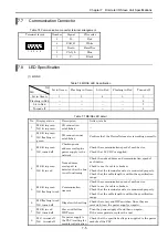
Page 23: ...tion Specifications Table 4 2 Communication Specifications Item Specification Communication protocol Conforms to DeviceNet release 2 0 Master module and Slave controller Conforms to DeviceNet release 1 4 Discrete I O slave unit Supported connections 1 Poll I O connection 2 Bit strobe I O connection only for master module and slave controller 3 Cyclic I O connection only for master module and slave...

Page 24: ...ged connector 5 Lock button This is used when removing the module from the base unit After it is mounted on the base unit the attachment can be reinforced using screws In this case use M4 x 10 mm 0 39 in screws The DIP switch on the side of the module is covered by a protective cover as it is not used Do not remove the cover MODE select EH RMD is possible to select the LINK mode or REMOTE mode EH ...

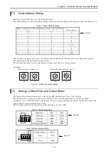
Page 25: ...de address NA1 NA2 NA4 NA8 NA16 NA32 0 OFF OFF OFF OFF OFF OFF 1 ON OFF OFF OFF OFF OFF 2 OFF ON OFF OFF OFF OFF 62 OFF ON ON ON ON ON 63 ON ON ON ON ON ON Baud Rate DR0 DR1 125 kbps OFF OFF 250 kbps ON OFF 500 kbps OFF ON NA32 NA16 NA8 NA4 MA2 NA1 DR1 DR0 ON Setting prohibited ON ON When setting the DIP switches turn off the power supply of the PLC and disconnect the module from the network The s...

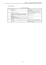
Page 26: ...e address overlap no power supply to the network Check the communication speed of each device Check that 24 V DC is supplied 4 MS lit in green NS lit in red Node address overlaps it is detected that the bus is not functioning Check the node address and communication speed of each device Check to see if a cable is broken Check that the terminal resistor is connected properly Check that the cable le...

Page 27: ...en Waiting for initialization Perform the I O assignment for the CPU Flashing twice in green PLC fault There is an error in the CPU Cancel the error of the CPU Flashing four times in green Link parameter error I O assignment unmatched for REMOTE station Check the transmission area and transmission size Read real I O assignment Flashing five times in green Module error Lit in red Internal microcomp...

Page 28: ...eset In this chapter it mentions about the way of operating the reset function from the user program of the above No 3 To execute the above No 3 the version of EH CPU and EH RMD must become as follows Table 5 10 Resetting function supporting EH CPU CPU type Version Note EH CPU308 316 Not supported EH CPU308A ROM VER A2 00 EH CPU316A ROM VER B2 00 EH CPU448 ROM VER C3 26 ROM VER C4 08 EH CPU448A EH...

Page 29: ... Sets the actual address of R L and M in this area using the ADRIO command 6 Transfer source destination header I O number In the software reset this area isn t used Sets 0 7 Size In the software reset this area isn t used Sets 0 1 Execution flag Set to 1 using a user program when performing software reset using FUN201 command When this command is complete the FUN201 command resets this to 0 2 Nor...

Page 30: ...ag the abnormal end flag of the FUN201 command R103 Uses as the flag which shows that the communication re start WR1003 HA55A WR1004 H100 ADRIO WR1005 R100 WR1006 0 WR1007 0 R7E3 After RUN 1 Scan ON FUN201 WR1000 R0 Software reset Starting R100 1 R103 0 R0 Software reset Starting TD0 15 sec wait 1s 15 WR1008 WRF0E9 AND HFF TD0 15 sec wait R101 FUN201 normally end WR1008 EH RMD status 0 TD0 15 sec ...

Page 31: ...ial internal output The supporting version can be confirmed from the value too Table 5 14 The supporting version for Explicit message from special internal output Supporting version Note WRF020 0121H and later WRF021 0103H and later for Slot0 WRF022 0121H and later WRF023 0103H and later for Slot1 WRF024 0121H and later WRF025 0103H and later for Slot2 2 CPU LINK area assignment The OUTPUT area fr...

Page 32: ...7 Service Data0 Service Data3 WL108 WL1108 Service Data2 Service Data63 WL126 WL1126 Service Data 62 CONTROL FLAGS MESSAGE DATA Service data is 64 bytes max Don t use WL127 WL1127 Don t use WL1FF WL11FF RX flag Message size WL300 WL1300 b0 b15 TX complete flag WL301 WL1301 TXid WL302 WL1302 Status Reserved WL303 WL1303 Size Service WL304 WL1304 MAC ID WL305 WL1305 WL306 WL1306 Response Data1 Respo...

Page 33: ...e data too large for block 13 Reserved 14 Error Invalid size specified 15 Error Device Timed out 16 255 Reserved TXid When sending command set 1 byte data from 0 to 255 in this area When receiving response the data which is the same as TXid of the command is set By checking both TXid it is possible to relate the command message and the response message Size When sending command set the size of Ser...

Page 34: ...name Description H08 Service not supported The requested serivce was not inplemented or was not defined for this Object Class Instance H09 Invalid attribute value Invalid attribute data detected H0E Attribute not settable A request to modify a non modifiable attribute was received H10 Device state conflict The device s current mode state prohibits the execution of the requested service H11 Reply d...

Page 35: ... TX complete flag TX flag 0 6 If TX flag 0 TX complete flag 0 The response message reception procedure EH CPU User program EH RMD 1 If RX complete flag 0 Set the response message header and response data 2 Set the RX message size into the RX flag 3 If RX flag 0 Get the message 4 Set the RX message size into the RX complete flag 5 If RX flag RX complete flag RX flag 0 6 If RX flag 0 RX complete fla...

Page 36: ...ation operation time Class 100 H0064 Instance 1 H0001 Attribute 115 H73 Service H0E Get_Attribute_Single Command 2 It sets a maximum frequency to 60 Hz Class 101 H0065 Instance 1 H0001 Attribute 104 H68 Data 60 H003C Service H10 Set_Attribute_Sibgle 2 The operation time chart WL100 WL101 WL102 later WL300 WL301 WL302 later EH 150 DeviceNet Master module Inverter L100DN MAC ID 0 MAC ID 1 Command 1 ...

Page 37: ...r RUN TD0 Initializing Time out Initializing time out processing Initializing the TX flag WL301 0 WL101 WL300 R1 1 R7E3 1 scan ON after RUN Initializing the RX flag WL300 0 R1 WL300 0 DIF1 WL101 0 R1 0 R0 TD0 Initializing Time out 1s 5 R0 WL301 0 DIF0 R0 0 R1 Initialize routine ...

Page 38: ... WL103 H3 WL104 H1001 WL105 H65 WL106 H1 WL107 H3C68 WL108 H0 WM1 HD R11 Command 2 Setting the size of service data Setting the service and MAC ID Setting the Class Setting the Instance Setting the attribute Setting the TX message size DIF11 Command 1 Service H0E GET_ATTRIBUTE_SINGLE MAC ID 1 Class H0064 Instance H0001 Service data0 H6A Attribute Command 2 Service H10 SET_ATTRIBUTE_SINGLE MAC ID 1...

Page 39: ...TXid Setting TXid Setting TX message size into the TX flag Transmission Control routine DIF12 R11 Command 2 R100 TD1 Transmission time out 1s 5 TD1 Transmission time out R100 WL100 WL301 DIF13 WL100 0 R100 0 R102 1 Setting 0 into the TX flag Sending complete Reception standing by Abnormal transmission processing ...

Page 40: ...ut R102 WL300 0 DIF14 Response data analysis R103 1 R103 Reception time out WL101 WL300 R102 0 R104 1 Setting RX message size into the RX complete flag Abnormal reception processing R102 TD2 Reception time out 1s 5 R104 WL300 0 DIF15 WL101 0 R103 0 R104 0 Setting 0 into the RX complete flag ...

Page 41: ... VER 02 and later And EH CPU displays the detailed software version of EH RMD in the special internal output The supporting version can be confirmed from the value too Table 5 20 The supporting version for Explicit message from special internal output Supporting version Note WRF020 0128H and later WRF021 0105H and later for Slot0 WRF022 0128H and later WRF023 0105H and later for Slot1 WRF024 0128H...

Page 42: ...t Word Double word Usable I O X Y R L M TD SS CU CT WX WY WR WL WM TC DX DY DR DL DM Constant Other s Argument Function This is to execute explicit command for EH RMD module Put this command without any contact together with FUN 163 command Caution Argument s is dummy parameter Assign to WR WM or WL Actual address is not influenced anything by this command If EH RMD module is not mounted operation...

Page 43: ...ending area address ADRIO command 4 4 Receiving area address ADRIO command 5 5 Sending error code 6 6 Receiving error code 7 1 Slot No for 2nd EH RMD H13 1 Slot No for 4th EH RMD H14 2 Control flag address ADRIO command H15 3 Sending area address ADRIO command H16 4 Receiving area address ADRIO command H17 5 Sending error code H18 6 Receiving error code 0 Number of EH RMD modules Maximum is 4 1 Sl...

Page 44: ...a 1 Service data 0 Max 64 byte for service data Service data 63 Service data 62 Sending error code Error code Size Service data sending area from s 4 to s n size with byte unit If the byte size is odd number the last byte is stored in lower byte Error code Name Remarks 0001H Timeout error Detected by EH RMD timeout 3 sec 0002H Data size error Detected by EH RMD 0003H Mail box error Detected by EH ...

Page 45: ...e sending completed properly 0002H Message being sent 0004H Node off line error Detected by EH RMD 0005H DeviceNet port off line Detected by EH RMD 0006H Invalid Txid Detected by EH RMD 0007H Txid duplicated Detected by EH RMD 0009H sending receiving buffer full Detected by EH RMD 000CH Response data size over Detected by EH RMD 000EH Size error Detected by EH RMD 000FH Response time out error Det...

Page 46: ...H0001 Attribute 104 H68 Data 60 H003C Service H10 Set_Attribute_Sibgle EH 150 DeviceNet Master module Inverter L100DN MAC ID 0 MAC ID 1 Inverter L100DN MAC ID 5 MAC ID 0 WR100 2 WR101 0 ADRIO WR102 R100 ADRIO WR103 WR200 ADRIO WR104 WR300 WR107 3 ADRIO WR108 M0 ADRIO WR109 WM200 ADRIO WR10A WM300 FUN 163 WR100 R7E3 1 scan ON after RUN WR100 Number of Master WR101 Master 1 Slot No WR102 Specified R...

Page 47: ...202 100 WM203 1 WM204 H3C68 WM205 0 R7E3 1 scan ON after RUN WR200 size 1 WR201 Service MAC ID WR202 Class WR203 Instance WR204 Attribute Explicit command setting for L100DN MAC ID 5 R0 Send command to MAC ID 1 R100 R1 Send command to MAC ID 5 M0 FUN 162 WR0 R7E3 R100 Control flag to MAC ID 1 DFN0 R0 RES R M0 Control flag to MAC ID 5 DFN1 R1 RES R R0 Send command to MAC ID 1 DFN2 Receiving data an...

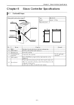
Page 48: ...ion Remark 1 LED Displays the network status and error information 2 DIP switch 1 Sets the node address and baud rate 3 Reset switch Resets the module 4 Communication connector Connects to the network Use the packaged connector 5 DIP switch 2 Sets to Hold Clear output for the output module on the EH IOCD 6 Lock button This is used when removing the module from the base unit After it is mounted on ...

Page 49: ...nsumption 450 mA max 6 Current consumption on communication side 80 mA max 7 Self diagnosis System ROM RAM check watchdog timer check Table 6 2 Supporting module list Input size Output size Type Word Byte Word Byte I O assign reference EH XD8 EH XD16 EH XA16 EH XAH16 1 2 0 0 X16 EH XD32 2 4 0 0 X32 EH XD64 4 8 0 0 X64 EH PT4 4 8 0 0 WX4W EH AX44 EH AX8V EH AX8H EH AX8I 8 16 0 0 WX8W EH YT8 EH YT16...

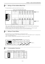
Page 50: ...reset Set the baud rate in such a way that all the devices on the network communicate at the same speed Set the node addresses for the other devices in such a way that they do not overlap 6 4 Setting of Output Status The output status is set by the DIP switches on the side of the module This status specifies whether to clear or hold the output data to the output module in case of a communication e...

Page 51: ...o power supply to the network Check the communication speed of each device Check that 24 V DC is supplied 4 MS lit in green NS lit in red Node address overlaps it is detected that the bus is not functioning Check the node address and communication speed of each device Check to see if a cable is broken Check that the terminal resistor is connected properly Check that the cable length is within the ...

Page 52: ...ber is indicated by the number of flashes in green Replace the faulty module Flashing twice in red I O module not supported Remove the module that is not supported Flashing three times in red Incorrect number of I O points Set the input output data so that it is 256 words or less Flashing four times or more in red Module internal device error Turn the power supply off and then on again If the erro...

Page 53: ... connector for connecting the DeviceNet communication cable 5 Mounting holes 2 locations These are used when the slave unit is attached to a panel etc Use M4 x 12 mm screws 6 Mounting lever for fixing to DIN rail This is used when attaching the unit to a DIN rail 7 Terminal block cover This is a cover attached to the terminal block area 8 Setting switch This switch is used for setting the slave un...

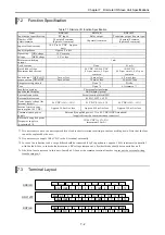
Page 54: ... Power supply voltage for internal circuit 24 V DC 10 15 24 V DC 10 5 24 V DC 10 15 Internal circuit power consumption 24 V DC Approx 100 mA or less Approx 200 mA or less Approx 100 mA or less Communication power supply Externally supplied power 11 to 25 V DC ODVA standard supplied from the communication connector Externally supplied power for power supply to S terminal 2 12 24 V DC 10 5 maximum 3...

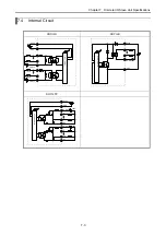
Page 55: ...e I O Slave Unit Specifications 7 3 7 4 Internal Circuit RDX16D RDY16R S24V S0V 0 7 COM0 Internal circuit 8 15 COM1 0 15 Internal circuit S24V COM0 S0V RDY16TP Internal circuit S24V S0V 0 7 S0 COM0 24V 8 15 S1 COM1 24V ...

Page 56: ...e address is 1 When the slave address is 63 7 6 Settings of Baud Rate and Output Status The baud rate is determined by bits 1 and 2 of the DIP switches see Table 7 3 as follows Set the baud rate in such a way that all the devices on the network communicate at the same speed In addition bit 4 of the DIP switches see Table 7 4 is for setting whether the module should hold or clear the output when a ...

Page 57: ...eck that 24 V DC is supplied 4 MS lit in green NS lit in red Node address overlaps it is detected that the bus is not functioning Check the node address and communication speed of each device Check to see if a cable is broken Check that the terminal resistor is connected properly Check that the cable length is within the specification range 5 MS lit in green NS flashing in red Communication timeou...

Page 58: ...ose or check whether the external devices are functioning LED stays lit although there is no input signal Input LED does not turn on although there is an input signal Replace the unit LED stays lit LED does not turn on The load is functioning although the output is not specified Replace the unit Output The load is not functioning although the output is specified Check whether the terminal block ha...

Page 59: ...roducts http www automation rockwell com The local office in every country can be accessed from the above site Please contact the following to obtain information about the installation and operation method of the above mentioned products http www automation rockwell com support For information on the EH RMD and PLCs in general please contact the Hitachi dealer where you made the purchase This chap...

Page 60: ...ign No according to the following table 1 Top Assign No of No 1 Link is WL0 and Top Assign No of No 2 Link is WL1000 Last Assign No setting EH RMD Last Assign No SOFTWARE VER 00 1 to FF 1000 to 10FF SOFTWARE VER 01 or later 1FF Fixed 11FF Fixed After downloading I O assignment to CPU module check the indication of STATUS LED on the EH RMD Link mode Solid Green Remote mode Solid Green or 4 times fl...

Page 61: ...t be supplied to the network and each device make sure to verify this in advance From the Start menu of Windows click Programs Rockwell Software RSLinx RSLinx S T E P 3 Selection of the Driver 1 Select the driver for the interface module to be used From the menu bar click Communications Configure Drivers ...

Page 62: ... Configure Drivers dialogue box is displayed From the Available Driver Types pull down menu click DeviceNet Drivers Click Add New The DeviceNet Driver Selection dialogue box is displayed Click Allen Bradley 1770 KFD and then Select ...

Page 63: ...s according to the actual system configuration Click OK If a display similar to the one to the following is shown the driver setting is completed If Status becomes Running like the following display the setting of the driver is completed Click Close Default is 62 When using already by the other node set the address which doesn t overlap ...

Page 64: ... message Unrecognized Device is displayed perform the registration of the EDS file explained later This is not a communication error Once the driver is set it is not necessary to change it in steps 2 and 3 unless the interface module or communication speed is changed When adding or deleting a slave device start the operation from step 4 S T E P 4 Startup of RSNetWorxTM 1 Start up RSNetWorxTM From ...

Page 65: ...d to the configurator Click Tools and then EDS Wizard For information on the EDS files for Hitachi made devices contact Hitachi s Sales Dept or download it from the following URL ODVA Home page http www odva org EH RMD has changed the EDS file used from SFOTWARE VER 03 The EDS Wizard will be displayed Click Next ...

Page 66: ... EDS file s and then Next Select the EDS file to be registered Enter the path of the file in Named and click Next To register via a selected folder check Register a directory of EDS files and enter the path to the folder in Named then click Next ...

Page 67: ...rm a syntax check of the EDS file Contact the manufacturer if a syntax error or warning is displayed Click Next The icon used in the configurator is displayed In order to change the icon click the icon and then Change icon Click Next ...

Page 68: ...Chapter 8 Starting Up 8 10 Click Next Click Finish ...

Page 69: ... click or drag and drop it Display the properties of the device and set the node address Interface modules are also treated as devices that have one node address but it is not necessary to register them in this step Register master slave devices that perform actual I O communication When all devices are registered proceed to Step 7 This icon indicates Off line ...

Page 70: ...ch for each device connected to the network It takes approximately 30 seconds to search for all the node addresses Click Cancel to end the search This causes no problem even if the search for all node addresses has not been finished Interface modules are also treated as devices that have one node address but it is not necessary to register them in this step This icon indicates On line ...

Page 71: ...P 7 Creation of a scan list 1 Register the master as well as all slaves with which the I O communication is performed Set the mode to off line if the on line mode is set Right click or double click the EH RMD to display the properties ...

Page 72: ...pping of I O data to WL described later without checking Automap on Add 2 Set the I O communication type and I O data size Make sure to select an I O communication type supported by the device I O data size must be set up in the byte unit Refer to the Table 6 2 The default I O data size of the EH IOCD is 8 bytes for both input and output Make sure to set the same size as for the mounted module It ...

Page 73: ... YTP32 EH CU EH YTP64 4 6 8 18 bytes 3 Mapping of input data Display the Input tag and 1 click each device followed by 2 AutoMap First enter the offset address in Start Byte then it becomes possible to map the input data to the selected area The maximum input size of the EH RMD is 512 bytes Set Start Byte in such a way that this size is not exceeded The data mapped in the Input tag is mapped to th...

Page 74: ... WL area as follows in case of LINK mode WL0 WL1 If the EH RMD is mounted in the slot corresponding to the second link area the mapping can be started from WL1000 This completes the creation of the scan list Click OK and exit the property screen of the EH RMD Caution When mapping the EH IOCD set the correct sizes of the I O modules to be mounted Data will not be input or output if the sizes are se...

Page 75: ...he device there is a possibility that a warning or error may be generated the data should therefore be downloaded directly to the EH RMD by clicking Download to Device The confirmation dialogue box is displayed click Yes This completes the setting in RSNetWorx Verify that the network status LED NS of the EH RMD and each slave device is lit in green The configuration data is stored in the FLASH mem...

Page 76: ...the configurator Figure 9 2 illustrates a system example configured for the purpose of sharing information of each PLC by making each EH RMD run as master and or slave In DeviceNet a slave device cannot communicate with multiple masters Thus unlike a common CPU link system it cannot send data to multiple PLCs Figures 9 3 and 9 4 show how to use the link area of the H series CPU link module and the...

Page 77: ...ure 9 4 Link system using the slave mode Master Slave Slave WL200 Slave Reception area Transmission area PLC2 Slave link area PLC3 Slave link area PLC4 Slave link area PLC1 Master link area PLC1 transmission PLC2 transmission PLC4 transmission PLC3 transmission Same set as above Copy by the user program of PLC1 Same set as above PLC2 transmission PLC4 transmission PLC3 transmission PLC1 transmissi...

Page 78: ...s required for each PLC Therefore when sharing data using the EH RMD the data size will be limited to the value obtained from formula 1 256 words number of slave EH RMDs number of words that can be shared by each EH RMD formula 1 The transmission area for each EH RMD must be assigned so that it does not exceed the value calculated by formula 1 In the configuration shown in Figure 9 2 the maximum d...

Page 79: ... Chapter 8 for the basic operation method of RSNetWorx PLC2 transmission PLC1 transmission LINK area PLC1 Master LINK area PLC2 Slave LINK area PLC3 Slave LINK area PLC4 Slave 128byte 128byte 128byte 128 byte Figure 9 5 LINK system with slave mode Example PLC3 transmission PLC4 transmission PLC2 transmission PLC3 transmission PLC4 transmission PLC2 transmission PLC3 transmission PLC4 transmission ...

Page 80: ...Chapter 9 Slave Mode 9 5 S T E P 1 Enabling the slave mode Double click PLC2 and display Properties Display the Module tag and click Slave Mode ...

Page 81: ...the transmission reception data in the Input and Output tags Select the device and click AutoMap Then click OK to finish the setting on the slave station side Specify the offset from WL0 for Start Byte in the Output tag Specify the offset from WL200 for Start Byte in the Input tag Repeat the operation above for PLCs 3 and 4 ...

Page 82: ... click PLC1 and display Properties Display the Scanlist tag and move the devices from Available Devices to Scanlist Click Edit I O Parameters for each of the devices moved to Scanlist and check the I O data size It is possible to view the information of each slave set in Step 1 ...

Page 83: ...Chapter 9 Slave Mode 9 8 Map the transmission reception data in the Input and Output tags Select a device and click AutoMap Then click OK ...

Page 84: ... 5 4 3 2 1 0 Error Code 00 15 0 01 31 Active node 16 02 47 32 03 63 48 04 15 0 05 31 Faulty node 16 06 47 32 07 63 48 08 Node No Master Node status 09 Node No Slave Node status 0A Node No Slave Node status 0B Node No Slave Node status 0C Node No Slave Node status 0D Node No Slave Node status 0E Node No Slave Node status 0F Node No Slave Node status 10 Node No Slave Node status 11 Node No Slave Nod...

Page 85: ...ode 16 02 47 32 03 63 48 04 15 0 05 31 Faulty node 16 06 47 32 07 63 48 08 Node 1 status Node 0 status 09 Node 3 status Node 2 status 0A Node 5 status Node 4 status Node 59 statu Node 58 status 26 Node 61 status Node 60 status 27 Node 63 status Node 62 status 28 Refresh time maximum 5D Refresh time minimum 5E Refresh time current 5F ...

Page 86: ...he EH RMD the node addresses of those that cannot be communicated with are displayed 10 3 4 Node Status Table 10 2 List of Node Status Value Description Node Description 0x00 OK or Not in scan list 0x54 NOT_YET_INITIALIZED 0x46 DUP_MAC_FAILURE 0x55 RECEIVE_BUFFER_OVERFLOW 0x47 SCANNER_CONFIG_ERROR 0x56 DEVICE_WENT_IDLE 0x48 DEVICE_COMM_FAILURE 0x57 SHARED_MASTER_ERROR 0x49 WRONG_DEV_TYPE 0x58 SHAR...

Page 87: ...with the slave devices registered in the scan list Therefore it is necessary to wait with turning the RUN switch of the CPU module on until after the MS and NS LEDs on the EH RMD turn on if input output communication with the slaves is performed immediately after the RUN start using the user program In addition if a ladder program is used use the master control in such a way that the user program ...

Page 88: ... 6 4 RDY16R RDY16TP Clear It is possible to specify either to clear or hold when a communication error occurred See Section 7 6 Other vendor s slave Depends on the vendor s specification Normally it is possible to specify either to clear or hold when a communication error occurred Caution When connecting with the other vendor s DeviceNet master EH IOCD and Discrete I O sometimes can not detect IDL...

Page 89: ...0 WL203 WX 440 WL204 WX 450 WL205 EH CU input most significant byte WX 460 WL206 EH AX44 least significant byte WX 470 WL207 WX 480 WL208 WX 490 WL209 WX 4A0 WL20A WX 4B0 WL20B WX 4C0 WL20C WX 400 WL20D EH AX44 most significant byte Result of mapping output data without offset REMOTE LINK b15 b0 WY 000 WL0 EH YT32 second least significant byte EH YT32 least significant byte WY 010 WL1 EH YT32 most...

Page 90: ...rom Ladder Editor for Windows The error check of a Link Remote is reflecting the data of the special internal output But in case of EH RMD the specification of the special internal output differs from the Link Remote module of H series Therefore if EH RMD is mounted and an error check is performed the check result is different from actual status of EH RMD ...

Page 91: ...line becomes longer Obtain the allowable current capacity Ic of a drop line from the following formula Ic 4 57 L L length of the drop line m The following table is the power specification to recommend in DeviceNet Table 12 1 DeviceNet power supply specification Item Specification Initial Tolerance 24 V DC 1 or adjustable to 0 2 Line Regulation 0 3 max Load Regulation 0 3 max Temperature Coefficien...

Page 92: ...nect the power supply shown in Section 12 3 may be used 5 If the power consumption calculated in step 1 above is greater than the maximum current capacity it is necessary to examine the position in greater detail in order to connect the power supply For more information see Section 12 4 Maximum current 8 7 6 5 4 3 2 1 0 0 50 100 150 200 250 300 350 400 450 Length of network m Figure 12 1 Maximum c...

Page 93: ...llows supplying a total power capacity twice that of the single power supply termination connection In this case the maximum current capacity should be calculated in each section Termination resistor Device Device Device Device Communication power supply Power supply tap Termination resistor Power supply tap Device Device Device Device Section 1 Section 2 Communication power supply Termination res...

Page 94: ...nication power supply at the center of the network Total power consumption value of section 1 0 3 A 0 1 A 0 3 A 0 7 A Total power consumption value of section 2 0 1 A 0 3 A 0 2 A 0 6 A Maximum allowable current value of section 1 2 01 A from Figure 12 1 Maximum allowable current value of section 2 2 01 A from Figure 12 1 In this configuration the total power consumption is within the maximum allow...

Page 95: ...nsumption value of section 2 1 0 A 0 1 A 0 15 A 0 1 A 1 35 A Maximum allowable current value of section 1 2 562 A linear interpolation between 100 m to 150 m Maximum allowable current value of section 2 1 722 A linear interpolation between 150 m to 200 m In this configuration the total power consumption is within the maximum allowable current value in each section Furthermore it can be determined ...

Page 96: ...drop 2 The function ground terminal FE terminal should use cable of 2 mm2 or more and Class D grounding 100 Ω or less The appropriate distance for ground cable is within 20 m 1 Grounding of instrumentation panel and relay panel can be shared 2 Avoid joint grounding with equipment that may generate noise such as high frequency heating furnace large scale power panel several kW or more thyristor exc...

Page 97: ...wing from the front 2 In case of fixing on the DIN rail Mount the backside of the slave unit onto the DIN 35 mm rail 1 Hook the claw attached to the back of the slave unit onto the DIN rail 2 Press the slave unit into the DIN rail until it clicks 3 After mounting the module check to make sure the slave unit is securely fixed 4 Secure the slave unit by installing commercially available DIN rail fix...

Page 98: ...r red and black according to the solderless terminal 13 5 How to Connect Communication Cables to Connectors Do not perform the wiring until the cable has been attached to the clamp terminals It is recommended to use a thin cable in case of multidrop connection Table 13 1 Applicable clamp terminals Number of lines Cable 1 2 Multidrop Signal line TMEVTC 1 25 11 Thick Cable Power line TMEVTC 2 11 Sig...

Page 99: ...t due to cable disconnection Make sure to make correct connection of signal lines power supply lines and shielding line Pay full attention when wiring so that neither signal lines power supply lines nor the shielding line will be pulled out during communication After wiring the communication cable be careful not to put excessive stress on the communication cable as well as the connector It may cau...

Page 100: ...its are used only one of them should be grounded with the shielding line Furthermore do not connect other communication power supply units with the shielding line Caution Do not ground the shielding line of the communication cable at multiple places in the network The grounding must be made at only one place Make sure to provide Class D grounding Provide a dedicated grounding separated from the po...

Page 101: ...us off communication timeout Module s LED display check Visual check RUN Lit in green Flashing in green 14 2 Items for Periodical Inspection Turn off the power for the external I O circuit and check the following items once every six months Table 14 2 Items for periodic inspection Part Item Check criteria Remark Configurator EH RMD Configuration data Must be the same as the actual network environm...

Page 102: ...ommunication power supply NO YES Is the connector tightened securely Tighten the connector securely NO YES Is the communication cable connected properly Set the communication cable properly NO YES Is the baud rate the same for all the devices on the network Make sure the baud rate is set accordingly NO YES Are the terminal resistors placed on both ends of the trunk line Attach termination resistor...

Page 103: ...g NO YES Is IO mapping correct Check the mapping from the configurator NO YES Is the node status normal Check the applicable node status in the special internal output NO YES Replace faulty parts if spare parts are available Contact Hitachi s Service Dept Is the output LED lit Check the output voltage Check the power supply voltage used for the load Check the external wiring YES NO Is IO mapping c...

Page 104: ...p 2 Client Group 2 Server UCMM Explicit Messaging Supported Yes DeviceNet Communication Data Fragmented Explicit Messaging Supported Yes DeviceNet Required Object Implementation IDentity Object 0x01 ID Description Get Set Value Limits 1 Revision 2 Max Instance 3 Number of Instances 4 Optional attributes list 5 Optional services list 6 Max ID of class attributes Attribute s 7 Max ID of instance att...

Page 105: ...6 MAC ID switch changed 7 Baud rate switch changed 8 MAC ID switch value Attributes 9 Baud rate switch value DeviceNet Services Parameter options Get_Attributes_All Get_Attributes_Single Allocate M S connection set Object Instance Services Release M S connection set Connection Object 0x05 ID Description Get Set Value Limits Attributes Not Supported DeviceNet Services Parameter options Object Class...

Page 106: ...rameter options Reset Delete Apply_Attributes Get_Attributes_Single Object Instance Services Set_Attributes_Single Connection Object 0x05 ID Description Get Set Value Limits Attributes Not Supported DeviceNet Services Parameter options Object Class Services Not supported Explicit Message Polled Bit Strobed Change of State Predefined M S Connections Cyclic ID Description Get Set Value Limits 1 Stat...

Page 107: ...rameter options Reset Delete Apply_Attributes Get_Attributes_Single Object Instance Services Set_Attributes_Single Connection Object 0x05 ID Description Get Set Value Limits Attributes Not Supported DeviceNet Services Parameter options Object Class Services Not supported Explicit Message Polled Bit Strobed Change of State Predefined M S Connections Cyclic ID Description Get Set Value Limits 1 Stat...

Page 108: ...path length 14 Produced connection path 15 Consumed connection path length 16 Consumed connection path Attributes 17 Production inhibit time DeviceNet Services Parameter options Reset Delete Apply_Attributes Get_Attributes_Single Object Instance Services Set_Attributes_Single Assembly Object 0x04 ID Description Get Set Value Limits Attributes Not Supported DeviceNet Services Parameter options Obje...

Page 109: ...orted Static Instance Type Dynamic ID Description Get Set Value Limits 1 Acknowledge Timer 2 Retry Limit COS Producing Connection Instance Ack List Size Ack List Data with Ack Path List Size Attributes 3 Data with Ack Path List DeviceNet Services Parameter options Delete Get_Attributes_Single Set_Attributes_Single Get_Member Add_Ack_Data_Path Object Instance Services Delete_Ack_Data_Path ...

Page 110: ...2 Server UCMM Explicit Messaging Supported Yes DeviceNet Communication Data Fragmented Explicit Messaging Supported Yes DeviceNet Required Object Implementation IDentity Object 0x01 ID Description Get Set Value Limits 1 Revision 2 Max Instance 3 Number of Instances 4 Optional attributes list 5 Optional services list 6 Max ID of class attributes Attributes 7 Max ID of instance attributes DeviceNet ...

Page 111: ...lue Limits 1 MAC ID 2 Baud rate 3 BOI 4 Bus off counter 5 Allocation information 6 MAC ID switch changed 7 Baud rate switch changed 8 MAC ID switch value Attributes 9 Baud rate switch value DeviceNet Services Parameter options Get_Attributes_All Get_Attributes_Single Allocate M S connection set Object Instance Services Release M S connection set Assembly Object 0x04 ID Description Get Set Value Li...

Page 112: ... options Reset Delete Apply_Attributes Get_Attributes_Single Object Instance Services Set_Attributes_Single Connection Object 0x05 ID Description Get Set Value Limits Attributes Not Supported DeviceNet Services Parameter options Object Class Services Not supported Explicit Message Polled Bit Strobed Change of State Predefined M S Connections Cyclic ID Description Get Set Value Limits 1 State 2 Ins...

Page 113: ... Parameter options Reset Delete Apply_Attributes Get_Attributes_Single Object Instance Services Set_Attributes_Single Connection Object 0x05 ID Description Get Set Value Limits Attributes Not Supported DeviceNet Services Parameter options Object Class Services Not supported Explicit Message Polled Bit Strobed Change of State Predefined M S Connections Cyclic ID Description Get Set Value Limits 1 S...

Page 114: ...ath 206624013003h 15 Consumed connection path length 4 16 Consumed connection path 202B2401h Attributes 17 Production inhibit time DeviceNet Services Parameter options Reset Delete Apply_Attributes Get_Attributes_Single Object Instance Services Set_Attributes_Single Acknowledge Handler Object 0x2B ID Description Get Set Value Limits Attributes Not Supported DeviceNet Services Parameter options Obj...

Page 115: ... Only Server UCMM Explicit Messaging Supported No DeviceNet Communication Data Fragmented Explicit Messaging Supported No DeviceNet Required Object Implementation IDentity Object 0x01 ID Description Get Set Value Limits Attributes Not supported DeviceNet Services Parameter options Object Class Services Not supported ID Description Get Set Value Limits 1 Vendor 74 2 Device type 7 3 Product code 1 4...

Page 116: ...utes_All Get_Attributes_Single Allocate M S connection set Object Instance Services Release M S connection set Connection Object 0x05 ID Description Get Set Value Limits Attributes Not Supported DeviceNet Services Parameter options Object Class Services Not supported Explicit Message Polled Bit Strobed Change of State Predefined M S Connections Cyclic ID Description Get Set Value Limits 1 State 2 ...

Page 117: ...pe 01h 3 Transport Class trigger 82h 4 Produced connection ID 5 Consumed connection ID 6 Initial comm characteristics 01h 7 Produced connection size 8 Consumed connection size 9 Expected packet rate 12 Watchdog time out action 13 Produced connection path length 0 14 Produced connection path 15 Consumed connection path length 0 16 Consumed connection path Attributes 17 Production inhibit time Devic...

Reviews: