Chapter 5 Master Module Specifications
5-7
5.6.2 Sample
program
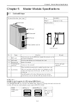
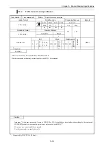
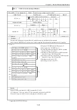
This sample program shows a way of resetting from the user program to this module.
So it is not the one to have considered an interlock and so on.
Before use, test sufficiently and use safety after the confirmation.
In this program, it uses the following internal output.
Table 5.12 Internal output
Internal output
Use
Note
R0
The software reset starting flag.
This flag is reset after 15 sec.
WR1000 -
WR1007
Used as the S parameter area to use in the FUN201 command.
WR1008
Set the node status of EH-RMD.
R100 -
R102
Used as the execution flag, the normal end flag, the abnormal end
flag of the FUN201 command.
R103
Uses as the flag which shows that the communication re-start.
WR1003 = HA55A
WR1004 = H100
ADRIO ( WR1005 , R100 )
WR1006 = 0
WR1007 = 0
R7E3
After RUN
1 Scan ON
FUN201 ( WR1000 )
R0
Software reset
Starting
R100 = 1
R103 = 0
R0
Software reset
Starting
TD0
15 sec wait
1s 15
WR1008 = WRF0E9 AND HFF
TD0
15 sec wait
R101
FUN201
normally end
WR1008 EH-RMD
== status
0
TD0
15 sec wait
R0 = 0
Set S parameter for the
FUN201 command.
The FUN201 command execution
Don't put an execution condition.
Set to "1" the starting flag of
FUN201 by the soft reset condition
formation.
DIF0
Set the node status of EH-RMD.
The I/O No. changes by the Node No.
When FUN201 finished normally,
judge the communication re-start
by EH-RMD status=0.
R103
communication
re-start
Software reset finished.
R102
FUN201
abnormally end


