background image


Version 1.0 09/08/2017 


http://www.inorea.com 

35 

No. 

Code 

Parameters 

Setting range 

Factory default  Change 

Reference page 

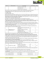
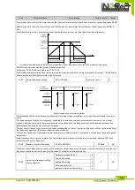
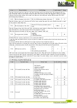
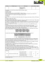
function selection 

1: Valid for both panel control 
and terminal control 
2: Valid for both panel control 
and communication control 
3: Valid for all control modes 

105.


F6.01 

Running status display 
parameters selection 

0 to 0xFFFF 
BIT0: Running frequency 
BIT1: Set frequency 
BIT2: Bus voltage 
BIT3: Output voltage 
BIT4: Output current 
BIT5: Running speed 
BIT6: Output power 
BIT7: Output torque 
BIT8: PID setting value 
BIT9: PID feedback value 
BIT10: Input terminal status 
BIT11: Output terminal status 
BIT12: Analog AI1 value 
BIT13: Analog AI2 value 
BIT14: Current stage of multi-
speed 
BIT15: Torque set value. 

03FF 


67 

106.


F6.02 

Stop status display 
parameters selection 

1 to 0x3FF 
BIT0: Set frequency 
BIT1: Bus voltage 
BIT2: Input terminal status  
BIT3: Output terminal status  
BIT4: PID setting value  
BIT5: PID feedback value 
BIT6: Analog AI1 value  
BIT7: Analog AI2 value  
BIT8: Current stage of multi-
speed  
BIT9: Torque set value. 
BIT10 to BIT15: Reserved 

0FF 


67 

107.


F6.03 

Speed display coefficient  0.1 to 999.9% 

100.0% 


68 

108.


F6.04 to 

F6.07 

Reserved 


5-1-9.F7 Group - Auxiliary function  

No. 

Code 

Parameter name 

Setting range 

Factory default 

Change 

Reference page 

109.


F7.00 

Jog running frequency 

0.00 to F0.08 
(maximum output 
frequency) 

5.00Hz 


68 

110.


F7.01 

Jog running acceleration time 

0.1 to 3600.0s 

Depends on 
models 


68 

111.


F7.02 

Jog running deceleration time 

0.1 to 3600.0s 

Depends on 
models 


68 

112.


F7.03 

Acceleration time 2 

0.1 to 3600.0s 

Depends on 
models 


68 

Summary of Contents for VFR-013

Page 1: ...Inoréa Automatisme et Industrie 9 rue du Lugan 33130 BEGLES contact inorea com www inorea com COMPLETE INSTRUCTIONS FREQUENCY INVERTER VFR 013 ...

Page 2: ...tion and operation of the frequency converter please carefully read this manual before installing it For any problem when using this product please contact your local dealer authorized by this company or directly contact this company our professionals are happy to serve you The end users should hold this manual and keep it well for future maintenance care and other application occasions For any pr...

Page 3: ...ize diagram 20 3 Chapter 3 Keyboard 21 3 1 Keyboarddescription 21 3 2 Keyboard Indicators 21 3 3 Description of operation panel keys 22 3 4 Examples of parameter settings 22 3 4 1 Password Settings 24 3 4 2 Motor parameter auto tunning 24 4 Chapter 4 Commissioning 26 5 Chapter 5 Function parameter 27 5 1 Menu grouping 27 5 1 1 d0 Group Monitoring function 28 5 1 2 F0 Group Basic function 29 5 1 3 ...

Page 4: ...terminals group 49 5 2 3 F2 Group Output terminals group 52 5 2 4 F3 Group Start and stop control group 54 5 2 5 F4 Group V F control group 55 5 2 6 F5 Group Vector control group 57 5 2 2 F6 Group Keyboard and display group 58 5 2 3 F7 Group Auxiliary function group 59 5 2 4 F8 Group Fault and protection group 61 5 2 5 F9 Group Communication parameter group 63 5 2 6 FA Group Torque control group 6...

Page 5: ...g 81 8 Chapter 8 Installation and Spare Circuit 84 8 1 Operating environment 84 8 2 Installation Direction andSpace 84 8 3 Wiring diagram 84 8 4 Main circuit terminal 86 8 4 1 VRF 013 main circuit terminal 86 8 4 2 Function Description of Terminals 86 4 1 control circuit terminal 86 4 5 1 control circuit terminal arrange 86 8 5 87 8 6 Control circuit terminals 87 8 5 1 Description of control circu...

Page 6: ...Version 1 0 09 08 2017 http www inorea com 6 11 Appendix I RS485 Communication Protocol 93 I 1 Introduction 93 I 2 Details 93 12 Product Information Feedback 104 ...

Page 7: ...on after unpacking Check if that packing container contains this unit one manual and one warranty card Check the nameplate on the side of the frequency inverter to ensure that the product you have received is the right one you ordered 1 1 1 Instructions on nameplate 1 1 2 Model designation 1 2 Safety Precautions Safety precautions in this manual are divided into the following two categories Danger...

Page 8: ...not let the lead wires or screws fall into the driver Otherwise which may cause damage to the driver Keep the driver installed in the place where less vibration avoid direct sunlight When two or more converters are installed in a cabinet please pay attention to the installation location ensure the good heat dissipation effect When wiring Danger Must comply with this manual s guidance any construct...

Page 9: ...it may cause an accident Danger The inverter s cover plate must close before power on Otherwise it may cause an electric shock Wiring of all external accessories must comply with the guidance of this manual please correctly wiring in accordance with the circuit connection methods described in this manual Otherwise it may cause an accident After energizing Danger Do not open cover plate after energ...

Page 10: ...nce task can be performed only when the inverter voltage is lower than AC36V generally that is two minutes after powering off Otherwise the residual charge from capacitor would cause personal injury Non well trained professional personnel is not allowed to perform repairs and maintenance of inverter Doing so may cause personal injury or damage to this unit After replacing the inverter parameter se...

Page 11: ... improving power factor is installed in the output side which easily cause the inverter instantaneous overcurrent or even cause damage to the inverter Please do not use 7 Contactor or switch used in the inverter input output terminals If contactor is installed between power supply and inverter the contactor is not allowed to start stop the inverter Necessarily need to use the contactor to control ...

Page 12: ...g to the motor rated current 2 The cooling fan and the rotor shaft for non inverter motor are coaxially connected the fan cooling effect is reduced when the rotational speed is reduced therefore when the motor works in overheating occasions a strong exhaust fan should be retrofitted or replace non inverter motor with the inverter motor 3 The inverter has built in the adaptive motor standard parame...

Page 13: ...ational Electrical Safety and other relevant standards Do not shut down power off by pulling switch and only cut off the power until the motor stopping operation 8 It is required to add the optional input filter attachment so as to meet CE standards 1 4 Scope of applications This inverter only applies to typical industrial three phase AC asynchronous motor This inverter can only be used in those o...

Page 14: ...nput Current A Rated output current A Adaptive motor Power KW VFR 013M2 0K4 Single phase 220V 10 0 4 5 4 2 5 0 4 VFR 013 M2 0K75 0 75 8 2 4 0 0 75 VFR 013 1K5 1 5 14 0 7 0 1 5 VFR 013T4 0K4 Three phase 380V 10 0 4 2 0 1 2 0 4 VFR 013T4 0K75 0 75 4 3 2 5 0 75 VFR 013T4 1K5 1 5 5 0 3 8 1 5 VFR 013T4 2K2 2 2 5 8 5 1 2 2 Note 380V series brake unit is standard accessory 220V series brake unit is optio...

Page 15: ...ot m th power custom V F curve Over load capability Rated Current 150 60 seconds Rated Current 200 1 seconds Slip compensation Slip compensation available Carrier Frequency 1kHz to 15kHz Start torque 0 5Hz 150 Open loop flux vector control Speed range 1 100 Open loop flux vector control Steady speed precision Speed control accuracy Open loop flux vector control 0 5 rated synchronous speed Torque r...

Page 16: ...rminals Emergency stop Interrupt controller output Wobbulate run Process control run Jog running Slow speed running Fault reset When the protection function is active you can automatically or manually reset the fault condition PID feedback signal Including DC 0 to 10V 0 to 20mA Output signal Running status Motor status display forward reverse program running status Fault output Relay contact capac...

Page 17: ...eous power down restart Less than 15 milliseconds continuous operation More than 15 milliseconds automatic detection of motor speed instantaneous power down restart Speed start tracking method The inverter automatically tracks motor speed after it starts Parameter protection function Protect inverter parameters by setting administrator password and decoding Display LED Keyboard Running message Mon...

Page 18: ...ust flammable gas oil mist water vapor drip or salt etc Altitude Below 1000m Pollution degree 2 Product Standard Product adopts safety standards IEC61800 5 1 2007 Product adopts EMC standards IEC61800 3 2005 Cooling method Forced air cooling 2 3 Dimensions Appearance and installation holes size 6 Nameplate 7 Air duct inlet 8 Fixing holes 4 Inverter power input terminals 5 Inverter output terminals...

Page 19: ...Version 1 0 09 08 2017 http www inorea com 19 2 3 1 VFR 013 Series ...

Page 20: ...Version 1 0 09 08 2017 http www inorea com 20 2 3 2 Keyboard size diagram JVFR 013 size diagram ...

Page 21: ... Forward running lamp ON means that the inverter is forward operating REV Reverse running lamp ON means that the inverter is reverse operating Hz Frequency Indicator Frequency unit of the inverter A Current Indicator Current unit of the inverter Correspondence that LED displays symbols and characters digits is as follows Digital display area Display letters Corresponding letters Display letters Co...

Page 22: ...ing Key Data or function code decending Run Key Used for running operation in the keyboard mode Stop Reset Key Press the key to stop running in running status press the key to reset in fault alarm status can be used to reset the operation the key is subject to function code F6 00 Enter Key Enter into levels of menu screen confirm settings Keyboard potentiometer F0 02 is set to 3 keyboard potentiom...

Page 23: ...menu from the third level menu by pressing PRG key or ENTER key The difference between the two keys press ENTER to return the second level menu and save parameters setting before returning and automatically transfer to the next function code press PRG to return directly to the second level menu do not save parameters setting and return to current function code Example 1 restore factory default 50 ...

Page 24: ... speed PID settings and PID feedback etc their display depends on function code F6 01 and switch and display the selected parameter by pressing key orderly Inverter powers off and then powers on again the displayed parameters are the selected parameters before power off 3 4 1 Password Settings The inverter has password protection when Y0 01 is non zero value that is user password password protecti...

Page 25: ...automatically calculate the motor s following parameters If the motor can completely disengage its load please select 2 asynchronous motor parameter comprehensive auto tunning for b0 11 and then press the RUN key on the keyboard panel Motor Selection Parameters Motor b0 06 Asynchronous motor stator resistance b0 07 Asynchronous motor rotor resistance b0 08 Asynchronous motor stator and rotor induc...

Page 26: ...nner setting F0 00 F0 00 Configure correctly motor parameters b0 01 to b0 05 group Select appropriate ac deceleration time setting F0 05 F0 06 Motor parameter auto tunning fault setting b0 11 Open loop flux vector control V F 0 2 Select run command channel setting F0 04 Select appropriate frequency command setting F0 02 Select motor start up mode setting F3 00 Start motor to run observe the phenom...

Page 27: ...meter value is the actual measured value can not be changed indicates that the parameter value can be changed when the inverter is running or stoped Factory parameters prohibit the user to operate indicates that the parameter factory default is none or the value is undefined Code Parameter Group Name Functional Description Reference page d0 Monitoring function group Monitoring frequency current et...

Page 28: ... Set frequency Inverter current actual setting frequency 0 01Hz 46 2 d0 02 DC bus voltage Detected value for DC bus voltage 1V 46 3 d0 03 Inverter output voltage Inverter actual output voltage 1V 46 4 d0 04 Inverter output current Inverter actual output current 0 1A 46 5 d0 05 Inverter output power Inverter actual output power 0 1kW 46 6 d0 06 Inverter output torque Inverter actual output torque p...

Page 29: ...me Setting range Factory default Change Reference page 21 F0 00 Control mode 0 Open loop flux vector control 1 Reserved 2 V F control 3 torque control 2 47 22 F0 01 Keyboard set frequency 0 00Hz to F0 08 maximum output frequency 50 00Hz 48 23 F0 02 Frequency command selection 0 keyboard setting 1 Analog AI1 setting 2 Analog AI2 setting 3 Panel potentiometer setting 4 AI1 AI2 setting 5 Multi speed ...

Page 30: ...cy upper limit 0 00Hz 52 33 F0 12 Running direction selection 0 default 1 opposite 2 reverse prohibited 0 52 34 F0 13 AVR function selection 0 Invalid 1 full valid 2 only invalid during deceleration 1 53 5 1 3 F1 Group Input terminals No Code Parameter name Setting range Factory default Change Reference page 35 F1 00 DI1 terminal function selection 0 No function 1 Forward run 2 Reverse run 3 Three...

Page 31: ...imit 0 00V to F1 10 0 00V 56 44 F1 09 AI1 lower limit setting 100 0 to 100 0 0 0 56 45 F1 10 AI1 upper limit F1 08 to 10 00V 10 00V 56 46 F1 11 AI1 upper limit setting 100 0 to 100 0 100 0 56 47 F1 12 Filter time of AI1 input 0 00s to 10 00s 0 10s 56 48 F1 13 AI2 lower limit 0 00V to F1 15 0 00V 57 49 F1 14 AI2 lower limit setting 100 0 to 100 0 0 0 57 50 F1 15 AI2 upper limit F1 13 to 10 00V 10 0...

Page 32: ...put voltage 6 Analog input AI1 value 7 Analog input AI2 value 8 Run speed 9 to 10 Reserved 0 59 60 F2 05 AO1 output lower limit 0 0 to F2 07 0 0 59 61 F2 06 Lower limit corresponds to AO1 output 0 00V to 10 00V 0 00V 59 62 F2 07 AO1 output upper limit F2 05 to 100 0 100 0 59 63 F2 08 Upper limit corresponds to AO1 output 0 00V to 10 00V 10 00V 59 64 F2 09 MO1 Turn on delay time 0 0 3600s 0 0s 60 6...

Page 33: ...ode Parameter name Setting range Factory default Change Reference page 76 F3 00 Start running mode 0 Directly startup 1 Speed tracking restart 2 First DC braking and then start 0 61 77 F3 01 Startup start frequency 0 00 to 10 00Hz 0 00Hz 61 78 F3 02 Hold time for start frequency 0 0 to 50 0s 0 0 s 61 79 F3 03 Braking current before start 0 0 to 150 0 0 0 62 80 F3 04 Braking time before start 0 0 t...

Page 34: ... F4 08 V F voltage point 3 0 0 to 100 0 0 0 65 95 F4 09 V F slip compensation limit 0 0 to 200 0 0 0 65 5 1 7 F5 Group Vector control group No Code Parameter name Setting range Factory default Change Reference page 96 F5 00 Speed loop proportional gain 1 0 to 100 20 65 97 F5 01 Speed loop integral time 1 0 01 to 10 00s 0 50 s 66 98 F5 02 Switching low point frequency 0 00Hz to F5 05 5 00Hz 66 99 F...

Page 35: ...f multi speed BIT15 Torque set value 03FF 67 106 F6 02 Stop status display parameters selection 1 to 0x3FF BIT0 Set frequency BIT1 Bus voltage BIT2 Input terminal status BIT3 Output terminal status BIT4 PID setting value BIT5 PID feedback value BIT6 Analog AI1 value BIT7 Analog AI2 value BIT8 Current stage of multi speed BIT9 Torque set value BIT10 to BIT15 Reserved 0FF 67 107 F6 03 Speed display ...

Page 36: ...evel detection value 0 00 to F0 08 maximum output frequency 50 00Hz 70 120 F7 11 FDT hysteresis detection value 0 0 to 100 0 FDT level 5 0 71 121 F7 12 Frequency reaches detection width 0 0 to 100 0 Set frequency 0 0 71 122 F7 13 Braking threshold voltage 115 0 to 140 0 standard bus voltage voltage level 220V 120 0 71 115 0 to 140 0 standard bus voltage voltage level 380V 130 0 5 1 10 F8 Group Fau...

Page 37: ... No Code Parameter name Setting range Factory default Change Reference page 134 F9 00 Communication baud rate setting 0 1200bps 1 2400bps 2 4800bps 3 9600bps 4 19200bps 5 38400bps 3 74 135 F9 01 Data bits parity settings 0 no parity N 8 1 for RTU 1 even parity E 8 1 for RTU 2 odd parity O 8 1 for RTU 3 no parity N 8 2 for RTU 4 even parity E 8 2 for RTU 5 odd parity O 8 2 for RTU 6 no parity N 7 1...

Page 38: ... AI2 setting 5 Multi segment torque setting 6 Remote communications setting Note Option 1 to 6 100 relative to two times of the rated current of inverter 0 76 143 FA 01 Keyboard set torque 200 0 to 200 0 rated current of inverter 50 0 77 144 FA 02 low speed torque compensation 0 000 1 000 0 050 77 145 FA 03 high speed torque compensation 0 000 1 000 0 000 77 5 1 13 Fb Group Control optimization No...

Page 39: ...E0 01 Sudden jump frequency range 0 0 to 50 0 relative to Wobbulate amplitude 0 0 79 159 E0 02 Wobbulate rise time 0 1 to 3600 0s 5 0 s 79 160 E0 03 Wobbulate fall time 0 1 to 3600 0s 5 0 s 79 5 1 15 E1 Group Multi speed control No Code Parameter name Setting range Factory default Change Reference page 161 E1 00 Multi speed 0 100 0 to 100 0 0 0 80 162 E1 01 Multi speed 1 100 0 to 100 0 0 0 80 163 ...

Page 40: ... E2 01 1 Analog channel AI1 setting 2 Analog channel AI2 setting 3 Panel potentiometer setting 4 Remote communications setting 5 Multi speed setting 0 83 179 E2 01 Keyboard preset PID setting 0 0 to 100 0 50 0 83 180 E2 02 PID feedback source selection 0 Analog channel AI1 feedback 1 Analog channel AI2 feedback 2 Panel potentiometer feedback 3 AI1 AI2 feedback 4 Remote communications feedback 5 AI...

Page 41: ... Virtual VDI1 Tens digit Virtual VDI2 Hundreds digit Virtual VDI3 Thousands digit Virtual VDI4 Ten thousands digit Virtual VDI5 00000 87 195 E3 06 VDI status setting Units digit Virtual VDI1 Tens digit Virtual VDI2 Hundreds digit Virtual VDI3 Thousands digit Virtual VDI4 Ten thousands digit Virtual VDI5 11111 87 196 E3 07 AI1_DI function 0 to 25 0 88 197 E3 08 AI2_DI function selection 0 to 25 0 8...

Page 42: ...0 s 89 5 1 18 b0 Group Motor parameters No Code Parameter name Setting range Factory default Change Reference page 211 b0 00 Inverter type 0 G type machine 1 Reserved 0 90 212 b0 01 Rated motor power 0 4 to 900 0kW Depends on models 90 213 b0 02 Rated motor voltage 0 to 460V Depends on models 90 214 b0 03 Rated motor current 0 1 to 2000 0A Depends on models 90 215 b0 04 Rated motor frequency 0 01H...

Page 43: ...ry 0 no operation 1 Restore factory settings excluding motor parameters 2 Clear fault history 3 Restore factory settings including motor parameters 4 Backup parameters 5 Restore from backup 0 91 224 y0 01 User password 0 to 65535 0 92 5 1 20 y1 Group Fault history search No Code Parameter name Setting range Factory default Change Reference page 225 y1 00 Type of the first two faults 0 to 22 0 92 2...

Page 44: ...Version 1 0 09 08 2017 http www inorea com 44 No Code Parameter name Setting range Factory default Change Reference page 232 y1 07 Output terminal status of current fault 0 93 ...

Page 45: ... output torque 1 Actual output torque percentage when the inverter running d0 07 Input terminal status DI input terminal status is currently displayed when it is converted into binary data one bit corresponds to one DI terminal input signal 1 indicates that the input terminal is high level signal 0 indicates that the input terminal is low level signal Bit0 Bit1 Bit2 Bit3 Bit4 DI1 DI2 DI3 DI4 DI5 B...

Page 46: ...ve one motor Such as machine tools centrifuges wire drawing machines injection molding machines and other loads The capacity of frequency inverter and motor should not differ much frequency inverter capacity can be 2 size bigger or 1 size smaller than motor capacity otherwise may lead to control performance degradation or the un normal operation of drive system 1 Reserved 2 V F control suitable fo...

Page 47: ...unication protocol F0 03 Keyboard and terminal UP DOWN setting valid and the inverter power failure with data storage 0 0 valid and the inverter power failure without data storage 1 UP DOWN setting invalid 2 Valid when running invalid when stop 3 Set the frequency through keyboard and keys and input terminals UP DOWN frequency setting increment frequency setting decrement function the setting can ...

Page 48: ...ter output is affected the inverter derates under high carrier frequency the leakage current of the inverter increases the electromagnetic interference on external increases The low carrier frequency has contrary the case described above the too low carrier frequency will cause the instability of low frequency operation the torque reduction even oscillation The inverter has been set reasonably bef...

Page 49: ... Note after the parameter is initialized the motor running direction will be restored to its original status When the system debugging is completed please use with caution where the change of motor steering is strictly prohibited F0 13 AVR function selection Invalid 0 1 Full valid 1 Only invalid during deceleration 2 AVR function that automatically adjusts the output voltage function When AVR func...

Page 50: ...i speed terminal 4 is high See E1 group Multi speed 4 Multi speed 3 Multi speed 2 Multi speed 1 BIT3 BIT2 BIT1 BIT0 16 Ac deceleration time selection terminals used to select acceleration and deceleration time group Terminals Ac deceleration time selection Parameters OFF Ac deceleration time 1 F0 05 F0 06 ON Ac deceleration time 2 F7 03 F7 04 17 Control command switch terminal when the command sou...

Page 51: ...07 Change rate of terminal UP DOWN frequency increment 0 01 to 50 00Hz s 0 50Hz s When the terminal UP DOWN is used to adjust the set frequency the rate of frequency change i e frequency change amount per second F1 08 AI1 lower limit 0 00V to F1 10 0 00V F1 09 AI1 lower limit setting 100 0 to 100 0 0 0 F1 10 AI1 upper limit F1 08 to 10 00V 10 00V F1 11 AI1 upper limit setting 100 0 to 100 0 100 0 ...

Page 52: ...arity of input terminal is negative Bit0 Bit1 Bit2 Bit3 Bit4 DI1 DI2 DI3 DI4 DI5 Bit5 Bit6 Bit7 Bit8 Bit9 Reserved Reserved Reserved Reserved Reserved 5 2 3 F2 Group Output terminals group Code Parameter name Setting range Factory default Change F2 00 MO1 output selection 0 to 10 1 F2 01 Reserved F2 02 Reserved F2 03 Relay output selection 1 Set value Function Description 0 No output The function ...

Page 53: ...s of rated inverter current 3 Output torque 0 to 2 times of rated motor current 4 Output power 0 to 2 times of rated power 5 Output voltage 0 to 1 2 times of rated inverter voltage 6 AI1 analog input value 0 to 10V 0 to 20mA 7 AI2 analog input value 0 to 10V 0 to 20mA 8 Running speed 0 to 2 times rated motor speed F2 05 AO1 output lower limit 0 0 to F2 07 0 0 F2 06 Lower limit corresponds to AO1 o...

Page 54: ...l output terminal As a pulse output the maximum frequency of output pulse is 10kHz see detailed information from F2 16 F2 16 MO1 pulse output selection 0 running frequency 1 set frequency 2 output current 3 output torque 4 output power 5 output voltage 6 AI1 input value 7 AI2 input value 8 running speed RPM 9 10 reserved M01 pulse output frequency range is 0 01kHz F2 20 maximum output pulse value ...

Page 55: ...king current the greater braking force F3 05 Stop mode selection Deceleration stop 0 0 Free stop 1 0 Deceleration stop if stop command is enabled the inverter will reduce output frequency in accordance with the deceleration method and defined deceleration time and finally stops when the frequency is reduced to 0Hz 1 Free stop if stop command is enabled the inverter will stop output at once Load wi...

Page 56: ...e after boosting is as shown below the torque boost can improve the characteristics of V F frequency torque Select the amount of torque according to the appropriate load size the large load can increase the boost but the boost value should not be set too large the torque boost is too large the motor will run over excitation the inverter output current increases the motor heats up and the efficienc...

Page 57: ...ad is applied during V F control so as to improve the mechanical properties of the motor hardness This value should be set to the rated slip frequency of motor the rated slip frequency is calculated as follows Rated slip frequency FB n p 60 Where FB is for the motor rated frequency its corresponding function code is b0 04 n is the motor rated speed its corresponding function code b0 05 P is the nu...

Page 58: ...rent corresponding to 100 0 5 2 2 F6 Group Keyboard and display group Code Parameter name Setting range Factory default Change F6 00 STOP RESET key stop function selection Valid only for panel control 0 3 Valid for both panel control and terminal control 1 Valid for both panel control and communication control 2 Valid for all control modes 3 As for fault reset STOP RESET key is valid at any situat...

Page 59: ...g acceleration time 0 1 to 3600 0s Depends on models F7 02 Jog running deceleration time 0 1 to 3600 0s Depends on models Defined the inverter s setting frequency and ac deceleration time when jogging Jog running start mode direct start up and jog running stop mode deceleration stop F3 05 0 Jog running acceleration time refers to the time required that the inverter accelerates from 0Hz to maximum ...

Page 60: ...inverter output transition time at zero frequency F7 09 Power terminals running protection selection Terminal running command is invalid when it powers on 0 0 Terminal running command is valid when it powers on 1 If the running command channel is set to terminal control the system automatically detects the status of the running terminals when the inverter powers on Terminal running command is inva...

Page 61: ...frequency outputs pulse signal within the positive and negative of detection width of the set frequency specifically as shown below 设定频率 频率达到检 测信号 t t 输出频率 Schematic diagram of frequency arrival detection amplitude F7 13 Braking threshold voltage 115 0 to 140 0 standard bus voltage 120 0 115 0 to 140 0 standard bus voltage voltage level 380V 130 0 The function code is to set the initial bus voltag...

Page 62: ... overload protection selection OFF 0 2 Ordinary motor with low speed compensation 1 Inverter motor without low speed compensation 2 0 OFF No motor overload protection be caution at this time the inverter has not overload protection to load motor 1 Ordinary motor with low speed compensation As the cooling effect of ordinary motor at low speed gets worse the corresponding electronic thermal protecti...

Page 63: ...ansfer rate between the host computer and the inverter Note the baud rate must be set to the same for the host computer and the inverter otherwise communication can not be achieved The larger baud rate the faster communication speed F9 01 Data bits parity settings 0 no parity N 8 1 for RTU 1 even parity E 8 1 for RTU 2 odd parity O 8 1 for RTU 3 no parity N 8 2 for RTU 4 even parity E 8 2 for RTU ...

Page 64: ...s digit of the function code LED is 1 the host computer of inverter responds read command only this way can improve communication efficiency When tens digit of the function code LED is 0 the inverter will not save the set value at power failure 5 2 6 FA Group Torque control group Code Parameter name Setting range Factory default Change FA 00 Torque setting mode selection Keyboard settings FA 01 0 ...

Page 65: ...illation suppression 0 to 500 5 Fb 04 High frequency threshold point of oscillation suppression 0 to 500 100 But most of the motors that run at certain frequency range occur current shocks sometime the motor can not run steadily even it can lead to the inverter overcurrent When Fb 07 0 the oscillation suppression is enabled if Fb 03 Fb 04 is set to very small both the effect of oscillation suppres...

Page 66: ...n means that the inverter output frequency swings up and down to set the frequency centering around the set frequency the locus the operating frequency on the timeline is as shown in figure which the swing amplitude is set by E0 00 when E0 00 is set to 0 the wobbulate will not work Figure 5 15 Wobbulate Operation Schematic Wobbulate amplitude the frequency of wobbulate operation is restricted by t...

Page 67: ...Multi speed 6 100 0 to 100 0 0 0 E1 07 Multi speed 7 100 0 to 100 0 0 0 E1 08 Multi speed 8 100 0 to 100 0 0 0 E1 09 Multi speed 9 100 0 to 100 0 0 0 E1 10 Multi speed 10 100 0 to 100 0 0 0 E1 11 Multi speed 11 100 0 to 100 0 0 0 E1 12 Multi speed 12 100 0 to 100 0 0 0 E1 13 Multi speed 13 100 0 to 100 0 0 0 E1 14 Multi speed 14 100 0 to 100 0 0 0 E1 15 Multi speed 15 100 0 to 100 0 0 0 ...

Page 68: ...inal 4 Multi speed terminal 3 Multi speed terminal 2 Multi speed terminal 1 Command setting Parameters OFF OFF OFF OFF Multi speed command 0 E1 00 OFF OFF OFF ON Multi speed command 1 E1 01 OFF OFF ON OFF Multi speed command 2 E1 02 OFF OFF ON ON Multi speed command 3 E1 03 OFF ON OFF OFF Multi speed command 4 E1 04 OFF ON OFF ON Multi speed command 5 E1 05 OFF ON ON OFF Multi speed command 6 E1 0...

Page 69: ...E1 15 When multi speed is selected as frequency source the 100 0 of function code E1 00 to E1 15 corresponds to maximum output frequency F0 08 Multi stage command is used for the function of multi speed also for PID setting source to meet the need to switch between different setting values E1 16 Section 0 given mode Function code E1 00 given 0 0 analog AI1 given 1 analog AI2 given 2 analog AI3 giv...

Page 70: ...tting can be achieved by setting the parameters of E1 group E2 01 Keyboard preset PID setting 0 0 to 100 0 50 0 When select E2 00 0 that is the target source is from keyboard setting you need to set this parameter The reference value for this parameter is the amount of system feedback E2 02 PID feedback source selection Analog channel AI1 feedback 0 0 Analog channel AI2 feedback 1 Panel potentiome...

Page 71: ...ing amount for example when increasing setting amount the feedback amount is always less than setting amount after the system is stable continue to increase the proportional gain and vice versa reduce the proportional gain repeat the above process until the static difference is relatively small it is hard to achieve zero static difference Integration time I when the deviation between feedback and ...

Page 72: ...ction 0 to 25 0 E3 01 VDI2 function selection 0 to 25 0 E3 02 VDI3 function selection 0 to 25 0 E3 03 VDI4 function selection 0 to 25 0 E3 04 VDI5 function selection 0 to 25 0 The function of virtual VDI1 to VDI5 is same as DI on the control panel they can be used as a multi functional digital inputs please refer to the introduction of F1 00 to F1 05 for detailed settings E3 05 VDI active mode Uni...

Page 73: ... the inverter is powered on it automatically enters the running state Using the following settings the function code E3 05 is used to set the state of VDI set VDI1 function as Forward Run E3 00 1 set that VDI1 terminal active mode depends on function code E3 06 xxx1 set VDI1 terminal status as valid E3 05 xxx1 set command source as terminal control F0 04 1 set start protection selection as termina...

Page 74: ...ive logic or negative logic 5 2 12 b0 Group Motor parameter group Code Parameter name Setting range Factory default Change b0 00 Inverter type 0 G type constant torque load type 1 Reserved 0 b0 01 Rated motor power 0 4 to 900 0kW Depends on models b0 02 Rated motor voltage 0 to 460V Depends on models b0 03 Rated motor current 0 1 to 2000 0A Depends on models b0 04 Rated motor frequency 0 01Hz to F...

Page 75: ...f the motor inertia otherwise it may occur overcurrent or overvoltage fault in the process of motor parameter auto tunning Set b0 11 to 2 and then press ENTER key to start the state of motor parameter auto tunning at this time the LED displays TUN and flashes press RUN key to start parameter auto tunning when TUN 0 TUN 3 is displayed TUN 4 motor starts running When the parameter auto tunning is co...

Page 76: ...cceleration overvoltage E oU1 8 Deceleration overvoltage E oU2 9 Constant speed overvoltage E oU3 10 Bus undervoltage fault E LU 11 Motor Overload E oL1 12 Inverter overload E oL2 14 output phase lose E oUT1 16 Inverter module overheating fault E oH2 17 External fault E SET 18 Communication fault E CE 19 Current detection fault E oCC 20 Auto tuning fault E tE 21 EEPROM operation fault E EEP 22 PID...

Page 77: ...e Parameter name Setting range Factory default Change MO1 Reserved Reserved R0 Reserved When the output terminal is ON the corresponding bit is 1 OFF for 0 This value can be used to understand the state of digital output signal at the sate of failure ...

Page 78: ...t and change 2 commutation notch immunity 3 harmonic input immunity 4 input frequency change 5 input voltage unbalance 6 input voltage fluctuation The tests shall be conducted strictly in accordance with the above requirements of IEC EN61800 3 and our products are installed and used according to the guideline of the Section 7 3 and can provide good electromagnetic compatibility in general industry...

Page 79: ...s error action For different interferences please refer to the following remedies 1 Generally the meters receivers and sensors for measuring and testing have more weak signals If they are placed nearby the inverter or together with the inverter in the same control cabinet they easily suffer from interference and thus generate error actions It is recommended to handle with the following methods awa...

Page 80: ...lines has higher harmonic it may cause resonance and thus result in leakage current If the thermal relay is used it may generate error action The solution is to reduce the carrier frequency or install output reactor It is recommended that the thermal relay shall not be installed in the front of the motor when using the inverter and that electronic over current protection function of the inverter s...

Page 81: ... output wiring 5 E oC2 Overcurrent when decelerating 1 Decelerated too quickly 2 Load inertia torque is large 3 The inverter power is small 4 Output phase loss 1 Increase deceleration time 2 Add suitable braking components 3 Choose the inverter with larger power 4 Check the output wiring 6 E oC3 Overcurrent at constant speed 1 Load mutation or abnormal 2 Mains voltage is low 3 The inverter power i...

Page 82: ...boost 4 Select the appropriate motor 12 E oL2 Inverter overload 1 Accelerated too quickly 2 Restart the motor that is rotating 3 Mains voltage is too low 4 Overload 1 Increase acceleration time 2 Avoid re starting at the state of stop 3 Check mains voltage 4 Choose the inverter with larger power 14 E oUT1 output phase lose 1 motor phase loss 2 module damage 1 check motor phase 2 check if module da...

Page 83: ...abnormal 1 Check the connector and re plug wire 2 Seek for service 3 Seek for service 4 Seek for service 20 E TE Motor parameter auto tunning fault 1 The motor s capacity does not match with the inverter s capacity 2 Rated motor parameters is set incorrectly 3 The learned parameters is different from the standard parameters 4 Auto tunning timeout 1 Replace the inverter model 2 Set rated parameters...

Page 84: ...osure to rain humidity shall be less than 90 RH non condensing 7 Never use in the dangerous environment of flammable combustible explosive gas liquid or solid 8 2 Installation Direction andSpace The inverter shall be installed in the room where it is well ventilated the wall mounted installation shall be adopted and the inverter must keep enough space around adjacent items or baffle wall As shown ...

Page 85: ...Version 1 0 09 08 2017 http www inorea com 85 ...

Page 86: ...le phase connects to R T Ground terminals Ground terminals P RB Braking resistor terminals Connect to braking resistor U V W Inverter output terminals Connect to three phase motor 4 1 control circuit terminal 4 5 1 control circuit terminal arrange 1 VFR 013CB板控制回路端子 TA TC TB DI1 DI2 DI3 DI4 DI5 DI7 SPA COM PLC 24V COM 10V AI1 GND DA1 DI6 Inverter output terminals Braking resistor terminals P RB R ...

Page 87: ...nel 2 Input impedance 22kΩ with voltage input 500Ω with current input AI2 GND Analog input terminal 2 1 Input range DC 0V to 10V 0 to 20mA depends on the selected JP3 jumper on control panel 2 Input impedance 22kΩ with voltage input 500Ω with current input Digital input DI1 TO DI5 Multifunction digital terminals 1 to 5 1 Opto coupler isolation compatible with bipolar input 2 Input impedance 2 4kΩ ...

Page 88: ...ppropriately it is best to lay the wiring inside metal tube When the inverter is additionally equipped with peripherals filter reactor etc firstly measure its insulation resistance to ground by using 1000 volt megger so as to ensure the measured value is no less than 4 megohms When the inverter need to be started frequently do not directly turn power off only the control terminal or keyboard or RS...

Page 89: ...ystem Fan Whether abnormal noise or vibration exists or not Visually and audibly check No abnormal Body Surrounding conditions Temperature humidity dust and harmful gases Visually check with smelling and feeling As per Section 2 1 Input outp ut terminals Voltage Inputs output voltage is abnormal Test R S T and U V W terminals As per standard specifications Main circuit Overall Whether these phenom...

Page 90: ...age The following actions must be taken if the inverter is not put into use immediately temporary or long term storage after purchasing It should be stored at a well ventilated site without damp dust or metal dust and the ambient temperature complies with the range stipulated by standard specification If the time that the inverter is set aside exceeds one year a charge test should be made so as to...

Page 91: ...or incandescent lights to charge frequency inverters When charge the DC bus capacitor of drive system by connecting power directly then the time should not be less than 60 minutes The operation should be carried on under the condition of normal temperature and without load and moreover should be added resistor in the power supply cycle 380V drive system use 1K 100W resistor When the power is less ...

Page 92: ...on caused the failure 2 2 Users without permission to repair or alteration caused by product failure 2 3 Users beyond the standard specifications require the use of the inverter caused by product failure 2 4 Users to buy and then fell loss or damage caused by improper handling 2 5 Because the user use environment device caused by aging lead to product failure 2 6 Due to the fault cause of earthqua...

Page 93: ...esponse of slave also adopts the same structure and contents including action confirmation returning the data and error checking etc If slave takes place the error while it is receiving information or cannot finish the action demanded by master it will send one fault signal to master as a response 2 Application Method The inverter will be connected into a Single master Multi slave PC PLC control n...

Page 94: ...nd of master slave will return a signal that is a response to master for the broadcasting information sent by master slave does not need to feedback a response to master 5 Communication data structure MODBUS protocol communication data format of VFR 013 series Inverter is divided into RTU remote terminal unit mode and ASCII American Standard Code for Information International Interchange mode 1 In...

Page 95: ...e default frame tail is CRLF 0x0D 0x0A In ASCII mode in addition to header and trailer the rest of all data bytes are sent in ASCII code firstly sent the high 4 bytes and then send the low 4 bytes In ASCII mode the length of data is eight bytes For A to F the uppercase ASCII code is adopted At this point the data adopts LRC parity the parity covers slave s address and data The sum of parity is equ...

Page 96: ...CHK values are to be calculated CRC CHK high order END T1 T2 T3 T4 When F9 05 is set to 1 START T1 T2 T3 T4 ADDR 01H CMD 03H Byte number 04H Data address 0001H high order 13H Data address 0001H low order 88H Data address 0002H high order 00H Data address 0002H low order 00H CRC CHK low order CRC CHK values are to be calculated CRC CHK high order END T1 T2 T3 T4 ASCII master command information STA...

Page 97: ...eceived CRC field if the two values are not equal then there is an error in the transmission The CRC firstly stores 0xFFFF and then calls for a process to deal with the successive eight bit bytes in message and the value of the current register Only the 8 bit data in each character is valid to the CRC the start bit and stop bit and parity bit are invalid During generation of the CRC each eight bit...

Page 98: ...ngs of the inverter Read and write function code parameters Some functional code is not changed only for the manufacturer use or monitoring the rules of labeling function code parameters address The group number and label number of function code is used to indicate the parameter address High byte F0 to FB F group A0 to AF E group B0 to BF B group C0 to C7 Y group 70 to 7F d group low byte 00 to FF...

Page 99: ...0 to FF For example Function code F3 01 can not be stored into EEPROM address indicates as 0301 function code E3 05 can not be stored into EEPROM address indicates as 4305 the address indicates that only writing RAM can be done and reading can not be done when reading it is invalid address For all parameters you can also use the command code 07H to achieve the function Stop Run parameters section ...

Page 100: ...nsion data it is the percentage of the maximum output frequency F0 08 for torque dimension data the percentage is F5 07 torque upper limit digital setting Control command is input to the inverter write only Command word address Command function 2000H 0001H Forward run 0002H Reverse run 0003H Forward Jog 0004H Reverse Jog 0005H Free stop emergency stop 0006H Stop 0007H Fault reset 0008H Jog Stop In...

Page 101: ... address Lock password command content 1F01H 55AAH Inverter fault description Inverter fault address Fault code Inverter fault information 8000H 0000 No fault E oUP 0001 Inverter unit U phase E oUP 0002 Inverter unit V phase E oUP 0003 Inverter unit W phase E oC1 0004 Acceleration overcurrent E oC2 0005 Deceleration overcurrent E oC3 0006 Constant speed overcurrent E oU1 0007 Acceleration overvolt...

Page 102: ...nse the slave device will respond corresponding function code and data address or sub function code If it is the exception response the slave device returns a code equivalent to the normal code but the first position is the logic 1 For example a message sent from one master device to one slave device is required to read a set of inverter function code address data it will produce the following fun...

Page 103: ... the authentication error message will be reported 04H Illegal function When the received function code from the host computer is a disallowed operation the slave in the wrong state may deal with such requests too 05H Illegal data value When the received data field includes in the disallowed values Note it does not mean the register data item to be stored includes an value unexpected by applicatio...

Page 104: ...ould appreciate your valuable feedback For your convenience please visit our website www inorea com and then click Technologies and Services and Download columns to submit your feedback information 1 Download the update product manuals you need 2 View the technical information on products such as operation instructions specifications and features FAQ etc 3 Share application cases 4 Technical advis...

Reviews: