Version 1.0 09/08/2017
http://www.inorea.com
73
Code
Parameter name
Setting range
Factory
default
Change
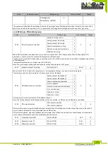
Tens digit
Virtual VDI2
(same as units
digit)
Hundreds digit
Virtual VDI3
(same as units
digit)
Thousands digit
Virtual VDI4
(same as units
digit)
Ten thousands digit
Virtual VDI5
(same as units
digit)
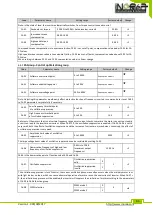
It is different from ordinary digital input terminal, the state of virtual VDI has two kinds of
setting, the selection depends on E3.06.
If the state of selection VDI is determined by the state of corresponding virtual VDO, the
availability of VDI depends on the valid or invalid VDO output, and VDIx only binds VDOx (x is 1 to
5) .
if the state of selection VDI is set by the function code, the status of virtual input terminals
can be determined through E3.05 binary bits respectively.
The following example illustrates the use of VDI. Example 1, to achieve the following
function: "Upon arrival of running frequency, the inverter will perform free stop" Using the
following settings method: set that the VDI state selection depends on VDO, set VDI1 function as
"free stop" (E3.00 = 8) ; set that VDI1 terminal active mode depends on VDO1 (E3.06 = xxx0) ; set
VDO1 output function as "Frequency Arrival" (E3.11 = 5) ;
When the inverter reaches the set frequency, the state of VDO1 is ON, at the time VDI1 input
terminal status is valid, if the inverter VDI1 receives the command of free stop, the inverter will
perform free stop.
Example 2, to achieve the following function: " the inverter is powered on, it automatically enters
the running state." Using the following settings: the function code E3.05 is used to set the state of
VDI, set VDI1 function as "Forward Run" (E3.00 = 1) ; set that VDI1 terminal active mode depends
on function code (E3.06 = xxx1) ; set VDI1 terminal status as valid (E3.05 = xxx1) ; set command
source as terminal control (F0.04 = 1) ; set start protection selection as terminal command active
(F7.08 = 0
)
;
After the initialization of inverter is completed, it is detected that VDI1 is valid and this
terminal corresponds to the forward run, which is equivalent to that the inverter receives one the
forward run command, the inverter begins to run forward.
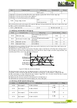
E3.07
AI1_DI function
0 to 25
0
★
E3.08
AI2_DI function selection 0 to 25
0
★
E3.09
Panel potentiometer_DI
setting
0 to 25
0
★
E3.10
AI_DI mode
Units digit: AI1
0: high level active
1: low level active
Tens digit: AI2 (same as units digit)
Hundreds digit: Panel potentiometer (same as
units digit)
000
★
This function code is used to set AI as DI, when AI is used as DI, when AI input voltage is
greater than 7V, AI terminal state is high level, when AI input voltage drops below 3V, AI terminal
status is low level. The voltage between 3V to 7V is regarded as the hysteresis, E3.10 is used to
determine whether AI high level or low level is active when AI is used as DI. The method of setting
AI as DI is same as the ordinary DI setting, please refer to the instructions on DI settings in F1
group.
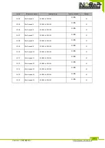
E3.11
VDO1 output function
0 to 10
0
☆
E3.12
VDO2 output function
0 to 10
0
☆
E3.13
VDO3 output function
0 to 10
0
☆
E3.14
VDO4 output function
0 to 10
0
☆
E3.15
VDO5 output function
0 to 10
0
☆

