6. Description of Parameters
- 192 -
6
6.10 Communication
The drive support communication links, such as Modbus, PROFIBUS-DP, CANlink (always valid), or
CANopen.
You can monitor and control of the AC drive, for example, view or modify function parameters by using
a host computer.
Make sure to set communication parameters correctly. Otherwise, communication may fail.
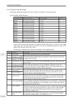
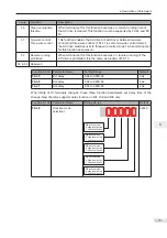
Function Code
Parameter Name
Setting Range
Default
F0-28
Serial port communication
protocol
0: Modbus protocol
1: PROFIBUS-DP or CANopen protocol
0
Fd-00
Baud rate
0000 to 6039
5005
Fd-01
Modbus data format symbol
0 to 3
0
Fd-02
Local address
0: Broadcast address
1 to 247
1
Fd-03
Modbus response delay
0 to 20
2
Fd-04
Serial port communication
timeout
0.0 (Invalid)
0.1 to 60.0
0.0
Fd-05
Modbus protocol selection
and PROFIBUS-DP data
frame
00 to 31
30
Fd-06
Current resolution read by
communication
0 to 1
0
Fd-08
CANlink communication
timeout time
0.0 (Invalid)
0.1 to 60.0
0
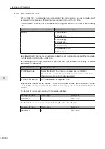
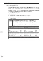
6.10.1 Read and Write Function Parameters
Ƶ
Read Function Parameters
For function parameters in groups F0 to FF and A0 to AF, the highest eight bits in
communication address indicate function code group, while the lowest eight bits indicate
hexadecimal number converted from SN in function code group.
For example, communication address of F0-16 is F010H, in which F0H indicates
function code group F0 and 10H is the hexadecimal number converted from 16.
Communication address of AC-08 is AC08H, in which ACH indicates function code group
AC and 08H is the hexadecimal number converted from 8.
To read desired function parameter, host computer needs to send a read command to
the AC drive. Here takes the Modbus protocol as an example to describe communication
process of reading the drive data.
For example, to read F0-10, read command is 01 03 F0 0A 01 DE D7 (hexadecimal). In
the command,
Ɣ
01H (settable): AC drive address
Ɣ
03H: read command
Ɣ
F00AH: communication address of F0-10
Ɣ
01H: number of function parameters
Ɣ
DED7H: CRC check
Summary of Contents for MD290 Series
Page 1: ......
Page 79: ...3 Electrical Installation 78 3 ...
Page 80: ...4 Operating Panel Keypad Display 4 1 Introduction 80 4 2 Inbuilt LED Operating Panel 80 ...
Page 92: ...5 Quick Setup 5 1 Get Familiar With Operating Panel 92 5 2 Setup Flowchart 93 ...
Page 227: ...7 Interfaces and Communication 226 7 ...
Page 285: ...10 Troubleshooting 284 11 ...
Page 349: ......
Page 350: ......

