221
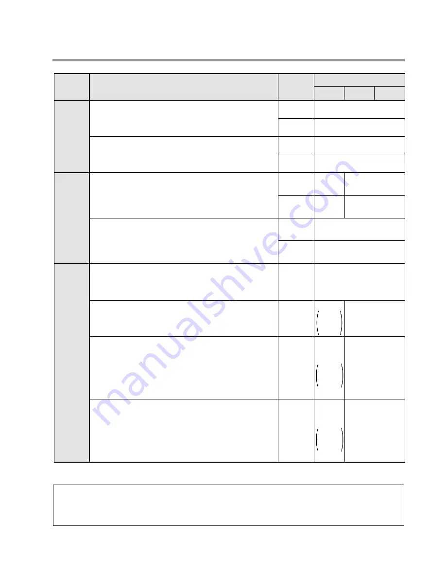
8-2. Table of Memory Areas
8-2. Table of Memory Areas
Notes:
• Timer/Counter contacts are represented in decimal.
• Word addresses are represented in decimal.
• The addresses for relay bits (X, Y, and R) are represented by a combination of word addresses (decimal)
and hexadecimals. The least significant digit is hexadecimal and the rest of the digits are decimal.
External
I/O relays
Internal
relays
Timer/
Counter
Item
Name and Function
Numbering
External input relay
This relay feeds signals to the programmable controller
from an external device such as a limit switch or
photoelectric sensor.
External output relay
This relay outputs the program execution result of the
programmable controller and activates an external
device such as a solenoid or motor.
Internal relay
This relay does not provide an external output and can
be used only within the programmable controller.
Special internal relay
This relay is a special internal relay which has specific
applications. This relay cannot be used for output. Use it
only as a contact. Refer to page 223, “8-3. Table of Special
Internal Relays”.
Timer contact
This contact is the output of a
TM
(Timer) instruction.
If a
TM
instruction has timed out, the contact with the
same number turns ON.
Counter contact
This contact is the output of a
CT
(Counter) instruction.
If a
CT
instruction has counted up, the contact with
the same number turns ON.
Timer
/
Counter set value
The timer/counter set value area is a memory area
where the set value of the
TM
/
CT
(Timer/Counter)
instructions is stored. Each timer/counter set value area
consists of 1 word (1 word = 16 bits). The address of this
memory area corresponds to the
TM
/
CT
instruction
number.
Timer
/
Counter elapsed value
The timer/counter elapsed value area is a memory area
where the elapsed value of the
TM
/
CT
(Timer/Counter)
instruction is stored. Each timer/counter elapsed value
area consists of 1 word (1 word = 16 bits). The address
of this memory area corresponds to the
TM
/
CT
instruction number.
64 points
(R9000 to R903F)
44 points
(C100 to C143)
144 words
(SV0 to SV143)
Symbol
1,008 points
(R0 to R62F)
63 words
(WR0 to WR62)
100 points
(T0 to T99)
144 words
(EV0 to EV143)
X (bit)
WX (word)
Y (bit)
WY (word)
R (bit)
WR (word)
R (bit)
T (bit)
C (bit)
SV (word)
EV (word)
208 points
(X0 to X12F)
13 words
(WX0 to WX12)
208 points
(Y0 to Y12F)
13 words
(WY0 to WY12)
4 words
(WR900 to WR903)
WR (word)
28 points
C100
to
C127
16 words
(WR0 to
WR15)
128
words
SV0
to
SV127
128
words
EV0
to
EV127
256 points
(R0 to
R15F)
C14/C16 C24/C40 C56/C72
Summary of Contents for FP1
Page 1: ...PROGRAMMABLE CONTROLLER FP1 is a global brand name of Matsushita Electric Works Hardware ...
Page 28: ...20 ...
Page 98: ...90 ...
Page 150: ...142 ...
Page 208: ...200 ...
Page 226: ...218 ...
Page 280: ...272 ...


