Outline
Subtracts the preset counter.
Program example
■
Operands
■
Explanation of example
■
Time chart
ON
OFF
X0
ON
OFF
X1
ON
OFF
C100
ON
OFF
Y0
•
•
•
#
#
#
#
#
#
#
#
#
#
ten times
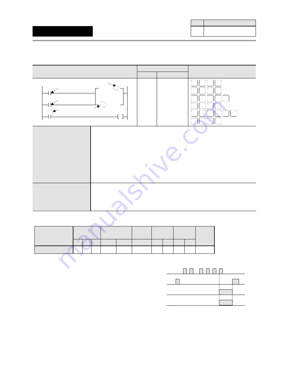
• In order to reset the counter, turns reset trigger X1
ON and then OFF.
• When the leading edge of the X0 is detected ten
times, counter contact C100 turns ON and then Y0
goes ON.
• The elapsed value EV100 is reset when X1 turns ON.
Timer/Counter
area
EV
Relay
SV
WR
WY
WX
Instruction
Preset (Set) value N/A N/A N/A
A
N/A
A:
N/A: Not Available
Register
DT
N/A
IY
IX
N/A N/A
H
K
A
N/A
Constant
Index
modifier
N/A
Index
register
Available
CT
Counter
Availability
Step
3
All series
Ladder Diagram
FP Programmer
II
key operations
Boolean Non-ladder
Address Instruction
0
X0
Count trigger
X1
C 100
Y0
CT 10
Reset trigger
Counter instruction number
100
Set value
1
5
ST
X-WX
ST
X-WX
1
WRT
ST
X-WX
ST
X-WX
0
WRT
CT
C-EV
OT
L-WL
AN
Y-WY
0
WRT
CT
C-EV
ST
X-WX
1
1
0
0
ENT
(BIN)
K/H
0
1
WRT
0
0
WRT
0
1
2
5
6
ST
X
0
ST
X
1
CT
100
K
10
ST
C 100
OT
Y
0
5-3. Description of Basic Instructions
119
Counter instruction number C14 and C16 series:
up to 128
C24, C40, C56, and C72 series: up to 144
The number of the
CT
instructions is shared with that of the
TM
instructions.
You can change the sharing of
TM
and
CT
instructions through the system
registers.
The default value of the
TM
and
CT
instructions is,
for C14 and C16 series:
TM
instruction: 0 to 99,
CT
instruction: 100 to 127
for C24, C40, C56, and C72 series:
TM
instruction: 0 to 99,
CT
instruction: 100 to 143
Preset (Set) value
All series: K0 to K32767
Decimal constant or counter set value area (SVn)* whose number is the same
as its timer instruction number (n)
*
“
SVn” can be specified only when the version of the CPU is 2.7 or later.
Summary of Contents for FP1
Page 1: ...PROGRAMMABLE CONTROLLER FP1 is a global brand name of Matsushita Electric Works Hardware ...
Page 28: ...20 ...
Page 98: ...90 ...
Page 150: ...142 ...
Page 208: ...200 ...
Page 226: ...218 ...
Page 280: ...272 ...


