Modbus Data Base
Publication PUB091-003-00_0119
43 of 76
7 MODBUS DATA BASE
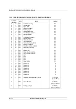
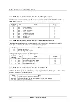
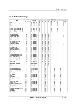
The data in the Modbus Module may be collected using a number of different Modbus function codes.
Similarly the commands to the MFU can be either register or discrete based. This inbuilt flexibility is
designed to allow for any host device to be able to access the actuator over a Modbus network in the
simplest way.
This section provides information on the function codes supported and the data that may be collected
or commands issued using those codes.
In all cases registers and discrete locations are numbered from 0 and do not include any offsets.
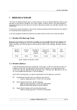
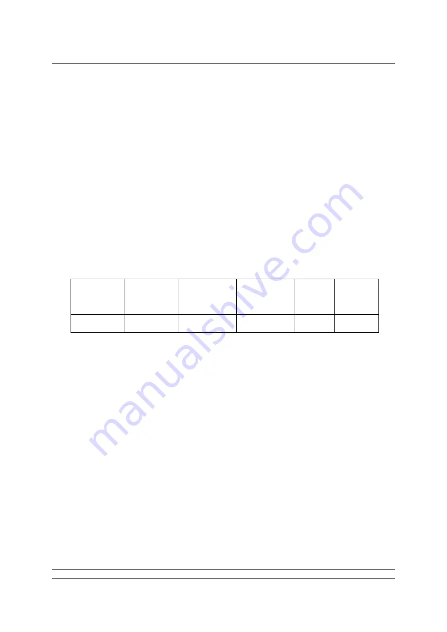
7.1 Modbus RTU Message Frame
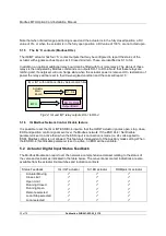
Message synchronisation is maintained by simulation, the receiving MFU monitors the elapsed time
between receipt of characters. If 3 and one-half character times elapse without a new character or
frame completion, then the next byte received will be the start of a new message and begin with the
address.
Modbus
Address
Function
Code
Register or
Discrete
Address
Number of
Registers or
Bits
Data
Field
CRC
Check
8 bits
8 bits
16 bits
16 bits
N bits
16 bits
7.2 Modbus Address
The Modbus Module allows slave addresses in the range 1 to 247 to be used for devices; the
addresses above 247 are reserved for special functions. Address 0 is recognised by all the
slaves and is used for global Broadcast messages only. This leaves 247 addresses for use by
the connected Modbus Modules on the data highway.
Note that the dual highway unit uses a single address for both highway connections.
Single RS-485 highway plus one analogue input channel
Address range supported = 0 to 247 (0 for broadcast)
Dual Independent Isolated –RS-485 highways
Address range supported = 0 to 247 (0 for broadcast)
Both channels must share the same address
Single RS-485 highway with inbuilt isolating repeater
Address range supported = 0 to 247 (0 for broadcast)
Fig 25: Modbus transaction format


