Setting Up the MFU
Publication PUB091-003-00_0119
63 of 76
9 SETTING UP AND MAINTAINING THE MODBUS MODULE
In most applications the majority of the default settings in the Modbus Module will be suitable for the
operation of the valve and need not be altered. However, in every case it will be necessary to alter the
address since the default should never be used within a live system (the default value is 247).
9.1 Using a Network Configuration Tool
Any device capable of writing register values can be used to configure the Modbus Module. Changes
to the actuator related parameter registers become active immediately they are altered. Changes to
the network related parameters usually require a power cycle of the actuator. In order to establish
communications to do this, the default network settings of address = 247, Baud rate = 9,600 and
Parity = none should be set in the Modbus Network Configuration tool. The individual register values
required may be different for each actuator and will depend on the application and process being
controlled as well as the actuator size, speed and other design features. Because the ROMpak and Q
actuators do not have a display, they can’t be configured using the infra-red setting tool, so they
should be set up over the network using a suitable configuration tool.
9.2 Setting up an IQ or IQT with the Setting Tool
The IQ / IQT and SI / EH actuators include an infra-red communication port for setting the actuator
performance, limit switches and so on. This communication link can be used to set some, but not all,
of the MFU parameter registers. The registers should still be checked with a Modbus host device to
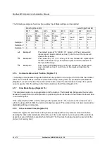
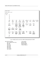
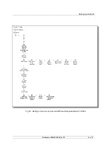
ensure optimum actuator and network compatibility. The diagram illustrates the access route through
the actuator menu screens to reach the settings that affect the MFU. Note that the
[Od]
function must
be set to
[OP];
if it is not then the card will not be able to control the actuator. For SI and EH actuators
there is another setting for
[OD]
to allow an additional direct hard-wired ESD, which is not affected by
the Auxiliary Input Mask setting. This setting for
[Od]
is
[OE].
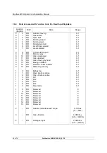
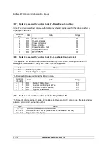
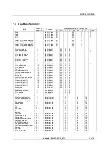
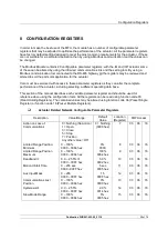
The parameters that may be set by using the Setting Tool and the infra-red link are listed below. The
available range for the deadband setting when using the setting tool is less than the range found using
the configuration tools. Parameters may only be altered if the actuator control knob is set to the Local
or Local Stop position.
Register
No.
Description
Range
Default
Value
7
Action on Loss of Communications
Nothing (No Action), Stop, Close,
Open, Position
Nothing
8
Limited Range Position Minimum
0 – 100%
0%
9
Limited Range Position Maximum
0 – 100%
100%
10
Deadband
0.0 – 9.9%
5.0%
11
Motion Inhibit Time
0 – 255 sec
3 sec
12
Aux Input Mask
0 – 255 (00 – FF hex)
15 (0F)
13
Communications Lost Position
0.0 – 100.0%
0.0%
22
Address
0 – 247
247
23
Baud Rate (baud)
300, 600, 1k2, 2k4, 4k8, 9k6,
19k2, 38k4
9k6
24
Parity (1 stop bit)
Odd, Even, None
None
Note:
- When altered, the new value will only take effect after the actuator power has been
cycled.


