SERIES IP330 INDUSTRIAL I/O PACK 16-BIT HIGH DENSITY ANALOG INPUT MODULE
___________________________________________________________________________________________
- 11 -
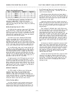
Table 3.6: Gain Select Binary Codes
Gain
Data Bits 7 to 2
Data Bit 1
Data Bit 0
1 Unused 0
0
2 Unused 0
1
4 Unused 1
0
8 Unused 1
1
The Gain Select register contents are undefined upon
power up or system reset
. The Gain Select registers
corresponding to all channels selected for conversion must be
written with the desired gain select binary codes prior to initializing
data conversions.
Mail Box Buffer (Read Only, 40H - 7EH)
The Mail Box Buffer is read-only, and contains 16-bit digitized
input channel values. The Mail Box Buffer has 32 storage
locations-one for each of the 32 channels supported by the IP330
in the single ended mode of operation. If the IP330 is used in the
differential mode of operation each of the 16 channels supported
are allocated two Mail Box Buffer locations.
See Table 3.2 which gives the Mail Box Buffer address
locations corresponding to each of the 32 channels (or 16
channels in differential mode). In differential mode the first
digitized data values will be stored in buffer locations 40H to 5FH
while the second digitized values are stored in buffer locations 60H
to 7EH. The storage of data in the Mail Box, in differential mode
will, continue to alternate between these two Mail Box sections.
The New Data register can be read to determine which Mail
Box Buffers contain updated digitized data. A set bit in the New
Data register indicates an updated digitized data value resides in
its corresponding Mail Box Buffer. In addition, the Missed Data
register can be read to determine if a Mail Box Buffer has been
overwritten with a new digitized value before the previous one had
been read. A set bit in the Missed Data register indicates that a
digitized data value has been lost or overwritten.
All register accesses to the IP330 require one wait state with
the exception of a read access to the Mail Box Buffer. A read
access to the Mail Box Buffer could take up to six wait states if a
read is issued while a hardware write of channel data to the same
Mail Box is currently underway. Most of the time, contention with
hardware writes is not an issue. In which case, one wait state is
required for a read access to the Mail Box.
MODES OF OPERATION
The IP330 provides five different modes of analog input
acquisition to give the user maximum flexibility for each
application. These modes of operation include: uniform
continuous, uniform single, burst continuous, burst single, and
convert on external trigger only. In all modes a single channel or a
sequence of channels may be converted. The following sections
describe the features of each and how to best use them.
Uniform Continuous-Mode
In uniform continuous mode of operation, conversions are
performed continuously (in sequential order) for all channels
between and including the Start and End Channel Values. The
interval between conversions is controlled by the interval timer
(Timer Prescaler and Conversion Timer as described in the
Conversion Timer Register section). The interval timer must be
used in this mode of operation.
After software selection of the uniform continuous mode of
operation, conversions are started either by an external trigger, or
by setting the software start convert bit. If the external trigger is to
be used bit-2 of the Control register must be set low to accept the
external trigger as an input signal.
Stopping the execution of uniform continuous conversions is
possible by writing 000 to the Scan Mode bits (8-10) of the Control
register. See the Control register section for additional information
on the Scan Mode control bits and the Control register board
address location.
When configured for differential input, the Mail Box functions
as a dual level data buffer. The first half of the Mail Box is used to
store all selected channel data for the initial pass through the
channels defined by the Start and End Value registers. The
second half of the Mail Box is then used to store the channel data
corresponding to the second pass though all selected channels.
Storage of channel data continues to alternate between the first
and second halves of the Mail Box Buffer. As seen in Table 3.2,
the first half of the Mail Box is defined by word addresses 40H to
5EH while the second half is defined by word addresses 60H to
7EH.
Interrupts can be enabled to activate after conversion of each
channel or the group of channels defined by the Start and End
Channel Values. If interrupts are configured to go active after the
conversion of each channel, the actual interrupt will be issued 8
µ
seconds after the programmed interval has lapsed. If interrupt
upon completion of a group of channels is selected, an interrupt
will be issued 8
µ
seconds after the interval time of the last
selected channel has expired.
If interrupts are selected to go active after conversion of each
channel be sure to program a large enough interval between
conversions to allow adequate time for execution of an interrupt
service routine. It may also be necessary to allow time for your
computer to perform other housekeeping operations between
servicing interrupts.

