SERIES IP330 INDUSTRIAL I/O PACK 16-BIT HIGH DENSITY ANALOG INPUT MODULE
___________________________________________________________________________________________
- 7 -
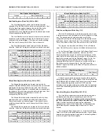
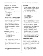
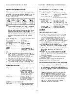
Table 3.1: IP330 ID Space Identification (ID) PROM
Hex Offset
From ID
PROM Base
Address
ASCII
Character
Equivalent
Numeric
Value
(Hex)
Field Description
01
I
49
All IP's have 'IPAC'
03 P
50
05 A
41
07 C
43
09
A3
Acromag ID Code
0B
11
IP Model Code
1
0D
00
Not
Used
(Revision)
0F
00
Reserved
11
00
Not Used (Driver
ID Low Byte)
13
00
Not Used (Driver
ID High Byte)
15
0C
Total Number of
ID PROM Bytes
17
5A
CRC
19 to 3F
yy
Not Used
Notes (Table 3.1):
1. The IP model number is represented by a two-digit code within
the ID space (the IP330 model is represented by 11 Hex).
I/O SPACE ADDRESS MAP
This board is addressable in the Industrial Pack I/O space to
control the acquisition of analog inputs from the field. As such,
three types of information are stored in the I/O space: control,
status, and data.
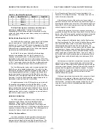
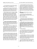
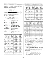
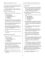
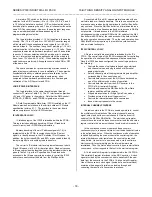
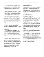
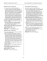
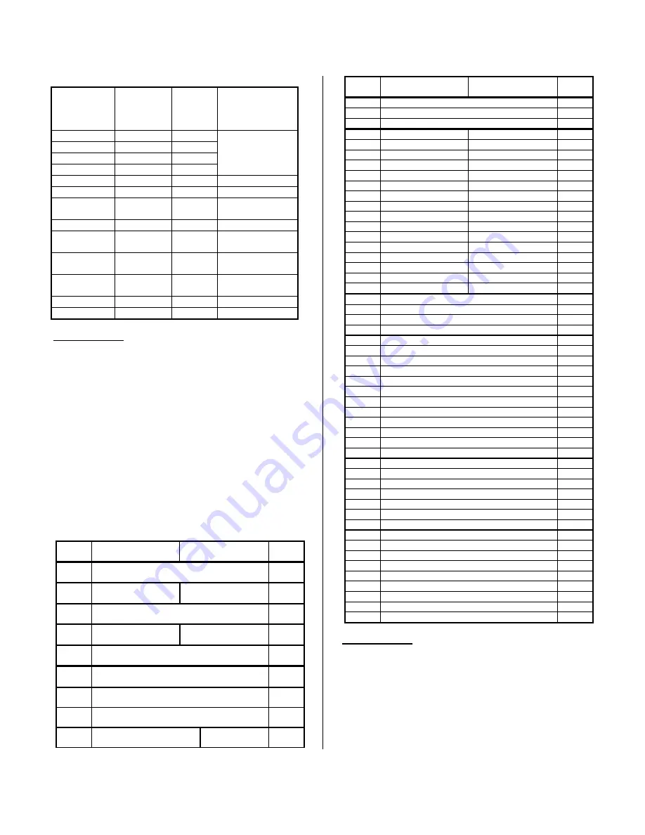
The I/O space may be as large as 64, 16-bit words (128 bytes)
using address lines A1 to A6, but the IP330 uses only a portion of
this space. The I/O space address map for the IP330 is shown in
Table 3.2. Note that the base address for the IP module I/O space
(see your carrier board instructions) must be added to the
addresses shown to properly access the I/O space. Both 16 and
8-bit accesses to the registers in the I/O space are permitted.
Table 3.2: IP330 I/O Space Address (Hex) Memory Map
2
Base
Addr+
MSB
D15 D08
LSB
D07 D00
Base
Addr+
00
Control Register
01
02
Timer Prescaler
Interrupt Vector
03
04
Conversion Timer
05
06
End Channel
Value
Start Channel
Value
07
08
New Data Register
Channels 0 to 15
09
0A
New Data Register
Channels 16 to 31
0B
0C
Missed Data Register
Channels 0 to 15
0D
0E
Missed Data Register
Channels 16 to 31
0F
10
Not Used
Bits15 to Bit 01
Start Convert
Bit-0
11
Base
Addr+
MSB
D15 D08
LSB
D07 D00
Base
Addr+
12
Not Used
1
13
↓
1E
Not Used
1
1F
20
Gain Select Ch 00
Gain Select Ch 01
21
22
Gain Select Ch 02
Gain Select Ch 03
23
24
Gain Select Ch 04
Gain Select Ch 05
25
26
Gain Select Ch 06
Gain Select Ch 07
27
28
Gain Select Ch 08
Gain Select Ch 09
29
2A
Gain Select Ch 10
Gain Select Ch 11
2B
2C
Gain Select Ch 12
Gain Select Ch 13
2D
2E
Gain Select Ch 14
Gain Select Ch 15
2F
30
Gain Select Ch 16
Gain Select Ch 17
31
32
Gain Select Ch 18
Gain Select Ch 19
33
34
Gain Select Ch 20
Gain Select Ch 21
35
36
Gain Select Ch 22
Gain Select Ch 23
37
38
Gain Select Ch 24
Gain Select Ch 25
39
3A
Gain Select Ch 26
Gain Select Ch 27
3B
3C
Gain Select Ch 28
Gain Select Ch 29
3D
3E
Gain Select Ch 30
Gain Select Ch 31
3F
40
Mail Box Ch 00 (SE or Diff. Mode)
3
41
42
Mail Box Ch 01 (SE or Diff. Mode)
43
44
Mail Box Ch 02 (SE or Diff. Mode)
45
46
Mail Box Ch 03 (SE or Diff. Mode)
47
48
Mail Box Ch 04 (SE or Diff. Mode)
49
4A
Mail Box Ch 05 (SE or Diff. Mode)
4B
4C
Mail Box Ch 06 (SE or Diff. Mode)
4D
4E
Mail Box Ch 07 (SE or Diff. Mode)
4F
50
Mail Box Ch 08 (SE or Diff. Mode)
51
52
Mail Box Ch 09 (SE or Diff. Mode)
53
54
Mail Box Ch 10 (SE or Diff. Mode)
55
56
Mail Box Ch 11 (SE or Diff. Mode)
57
58
Mail Box Ch 12 (SE or Diff. Mode)
59
5A
Mail Box Ch 13 (SE or Diff. Mode)
5B
5C
Mail Box Ch 14 (SE or Diff. Mode)
5D
5E
Mail Box Ch 15 (SE or Diff. Mode)
5F
60
Mail Box Ch 16 SE (Ch 00 Diff. Mode)
3
61
62
Mail Box Ch 17 SE (Ch 01 Diff. Mode)
63
64
Mail Box Ch 18 SE (Ch 02 Diff. Mode)
65
66
Mail Box Ch 19 SE (Ch 03 Diff. Mode)
67
68
Mail Box Ch 20 SE (Ch 04 Diff. Mode)
69
6A
Mail Box Ch 21 SE (Ch 05 Diff. Mode)
6B
6C
Mail Box Ch 22 SE (Ch 06 Diff. Mode)
6D
6E
Mail Box Ch 23 SE (Ch 07 Diff. Mode)
6F
70
Mail Box Ch 24 SE (Ch 08 Diff. Mode)
71
72
Mail Box Ch 25 SE (Ch 09 Diff. Mode)
73
74
Mail Box Ch 26 SE (Ch 10 Diff. Mode)
75
76
Mail Box Ch 27 SE (Ch 11 Diff. Mode)
77
78
Mail Box Ch 28 SE (Ch 12 Diff. Mode)
79
7A
Mail Box Ch 29 SE (Ch 13 Diff. Mode)
7B
7C
Mail Box Ch 30 SE (Ch 14 Diff. Mode)
7D
7E
Mail Box Ch 31 SE (Ch 15 Diff. Mode)
7F
Notes (Table 3.2):
1. The IP will not respond to addresses that are "Not Used".
2. All Reads and writes are 1 wait state (except a Mail Box read
issued simultaneously with an ongoing hardware write of a
new convert value. In this case a read cycle will include from
1 to 6 wait states).
3. The Mail Box is one level deep when using single ended
channels; it is two levels deep with differential mode.
This memory map reflects byte accesses using the “Big
Endian” byte ordering format. Big Endian is the convention used

