X90 mobile modules
198
X90 mobile system User's manual V 1.20 - Translation of the original manual
The raw data buffers (raw signal and FFT) from the module are transferred on request (buffer Flatstream in the
Tx direction) from the module via the buffer Flatstream (Rx direction) but only if the buffers were previously frozen
on the module with settings RequestBufferLock01 = 1 and BufferLockValid01 = 1. It is important to note that the
module refreshes the data points of the buffer Flatstream every X2X Link cycle. Once the transmission is complete,
the buffer from the stream needs to be "reassembled" on the PLC.
Registers for the buffer Flatstream
The following registers are needed to upload buffers:
"BufferInputSequence01" on page 206
"BufferRxByte01-05" on page 204
"BufferOutputSequence01" on page 205
"BufferTxByte01-04" on page 204
This results in an
"InputMTU"
of 5 bytes and an
"OutputMTU"
of 4 bytes for the buffer Flatstream.
Buffer upload procedure
Before a buffer can be uploaded from the module, the buffers on the module must first be locked by setting Request-
BufferLock01 = 1. The upload can only begin once the buffers have been locked by setting BufferLockValid01 = 1.
If a velocity buffer is uploaded, it only contains values if bit EnableVelocityCalculation of the corresponding channel
is set; otherwise, 0 is output. Bit EnableVelocityCalculation can be configured in register
"SensorConfig" on page
158
.
A buffer first needs to be requested from the module via the buffer Flatstream (Tx direction). Meaning:
■
BufferTxByte01: Value 0x83 (frame end and 3 bytes are valid)
■
BufferTxByte02: The requested buffer from the module
■
BufferTxByte03: High byte of the number of the values to be read (per 4-byte value)
■
BufferTxByte04: Low byte of the number of the values to be read (per 4-byte value)
The sequence is subsequently increased by 1. As soon as the sequence has been confirmed by the module, it
is important to set the number of valid bytes in BufferTxByte to 0; otherwise, the module interprets this as a new
request. The module can temporarily store up to 2 consecutive requests.
As soon as the module receives the request, it begins streaming the requested number of values from the speci-
fied buffer via the buffer Flatstream (Rx direction). Values are always transferred in 16.16 fixed data point format
(1/65536) with the high byte first. A scaling factor is transferred first. All other values are then multiplied by this
factor. With time signal buffers, the first value according to the scaling factor is always the oldest. With FFT buffers,
the first value according to the scaling factor is always 0 Hz. FFT buffers are only valid from the configured Min-
Frequency to the configured MaxFrequency of the respective signal (raw or envelope) and the respective channel.
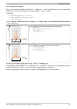
For the time and frequency intervals of individual values, see register
"MinFrequencyRaw" on page 188
or
"Min-
FrequencyEnvelope" on page 187
.
RequestBufferLock01 must be set to 1 throughout the entire uploading process. Once the requested buffers have
been uploaded from the module, the lock can be reset. In the module, the buffers are then once again filled with new
values. After some time has passed, they can be locked and uploaded again (see register
"Control" on page 157
).
Buffer number (dec.)
Channel
1
Channel
2
Channel
3
Channel
4
Buffer
Maximum number of values
(1 values = 4 bytes)
9
11
13
15
Raw signal
(filter value:
"MaxFrequencyRaw" on page 186
)
8193
1)
25
27
29
31
Envelope signal
(filter value:
"MinFrequencyEnvelope" on page 187
)
8193
66
70
74
78
FFT amplitude spectrum raw velocity signal
(filter value:
"MaxFrequencyRaw" on page 186
)
4097
67
71
75
79
FFT amplitude spectrum raw acceleration signal
(filter value:
"MaxFrequencyRaw" on page 186
)
4097
82
86
90
94
FFT amplitude spectrum envelope signal velocity
(filter value:
"MinFrequencyEnvelope" on page 187
)
4097
83
87
91
95
FFT amplitude spectrum envelope signal acceleration
(filter value:
"MinFrequencyEnvelope" on page 187
)
4097
1)
The first value in the buffer is the scaling factor.


