Chapter 4 Basic functions and System configuration
4 – 9
9)
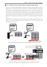
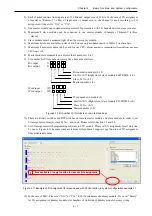
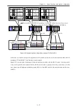
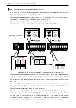
I/O numbers of I/O module on remote slave base are as follows. CPU accesses master module as not
remote module but as I/O module because I/O assignment of master is “Word 4W/4W”. So, I/O
number for I/O module on remote slave base becomes the I/O number of slot mounted master
module.
Bit
input X
Bit
output Y
Word
input
WX
Word
output
WY
Figure 4.13 I/O number of I/O module on remote slave base (I/O assignment for master: “Word 4W/4W”)
10)
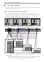
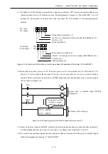
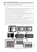
Bit number in module is from 0 to 95. Therefore, please use the word number such as WY6 and WY7 in
Figure 4.12 for the number that exceeds 95. In the case of using these No. as coil or contact in ladder
program, Please use internal output like as M/WM temporarily and transfer these data to external output
later as shown in Figure 4.14.
Figure 4.14 Sample program with bit I/O numbers that exceed 95
11)
There are Rotary switches and DIP-switches on remote master module and slave module in order to
set I/O assignment of master, slave St. No., and so on. Please refer to Section 3.1 and 3.2.
12)
You cannot use operation parameters for remote module and remote error flag area in internal output
when I/O assignment of master is “Word 4W/4W”.
Bit number in module (0-15)
Slot No. (0-7) (Right slot of slave module (EH-TRMLE) is 0.)
Unit No. (0-5)
Master number (0)
Word number in module (0)
Slot No. (0-7) (Right slot of slave module (EH-TRMLE) is 0.)
Unit No. (0-5)
Master number (0)
0
0
0
0
WY6 = WM60
WY7 = WM61
X15
Output data to internal output M/WM
temporarily
M608
X4
M60A
M60A
Transfer with word type
Transfer data from M600
to M60F to external
output with word type


