Pro II: Digital-I/O Modules
Pro II-DIO-32/1-TiCo Rev. E
ADwin
112
ADwin-Pro II
Hardware, manual Dec. 2018
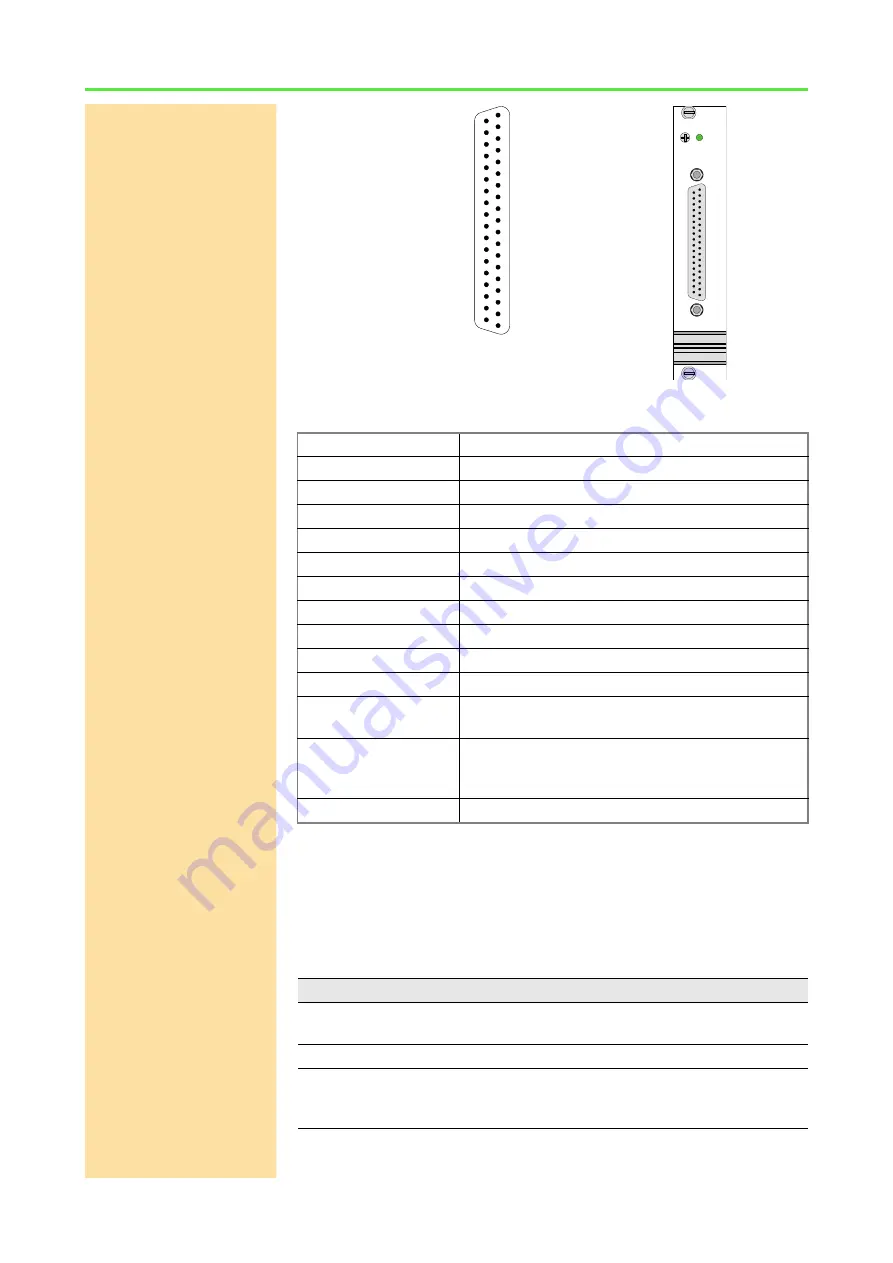
Fig. 96 – Pro II-DIO-32/1-TiCo Rev. E: Front panel and pin assignment
Programming
The module is comfortably programmed with
ADbasic
instructions. The
instructions are described in
ADbasic
online help and Pro II Software manual.
The include file
ADwinPro_All.inc
contains instructions for the following
functions:
Digital inputs
TTL logic
Input/output channels
32; each programmable via software as input/output
Pull down resistor
10k
Ω
V
IH
min. 2V
V
IL
max. 0.8V
I
IH
max. 1µA
I
IL
max. 0.01mA
Voltage range
-0.5V … +5.5V
Output current
max. ±32mA per channel via V
CC
or GND
Event input
TTL logic
Power up status
All channels as inputs
Input / output FIFO
Size: 511 value pairs
Frequency: 100MHz
TiCo
Prozessor type: TiCo1
Clock rate: 50MHz
Memory size: 28kiB PM internal, 28kiB DM internal
Connector
37-pin D-Sub female connector
Fig. 97 – Pro II-DIO-32/1-TiCo Rev. E: Specification
Function
Instructions
Configure input/outputs
P2_DigProg
P2_DigProg_Bits
Query input signals
P2_Digin_Long
Use latch register
P2_Dig_Latch
P2_Dig_Read_Latch
P2_Dig_Write_Latch
DIG I/O, Bit 1
DIG I/O, Bit 3
DIG I/O, Bit 5
DIG I/O, Bit 7
DIG I/O, Bit 9
DIG I/O, Bit 11
DIG I/O, Bit 13
DIG I/O, Bit 15
DIG I/O, Bit 17
DIG I/O, Bit 19
DIG I/O, Bit 21
DIG I/O, Bit 23
DIG I/O, Bit 25
DIG I/O, Bit 27
DIG I/O, Bit 29
DIG I/O, Bit 31
DGND
EVENT IN
DIG I/O, Bit 0
DIG I/O, Bit 2
DIG I/O, Bit 4
DIG I/O, Bit 6
DIG I/O, Bit 8
DIG I/O, Bit 10
DIG I/O, Bit 12
DIG I/O, Bit 14
DIG I/O, Bit 16
DIG I/O, Bit 18
DIG I/O, Bit 20
DIG I/O, Bit 22
DIG I/O, Bit 24
DIG I/O, Bit 26
DIG I/O, Bit 28
DIG I/O, Bit 30
DGND
+5V, <100mA (fused)
DGND
19
18
17
16
15
14
13
12
11
10
9
8
7
6
5
4
3
2
1
37
36
35
34
33
32
31
30
29
28
27
26
25
24
23
22
21
20
DIO 32-1
TiCo


