Function Blocks
UM353-1B
April
2012
3-82
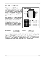
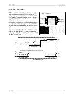
3.2.75 ROT_ - Retentive On Timer
ROT_
function blocks perform an on-delay timing
function with output states determined by inputs ON and
EN.
When input EN is low (0) outputs D and ND are low and
when input EN is high (1), the outputs will be determined
by the ON input and the elapsed time.
When ON goes high the elapsed time will start. Output D will
go high after ET (elapsed time) equals or exceeds the DLY
TIME. Output RT (remaining time) equals DLY TIME - ET.
If ON goes low, the elapsed time will stop at the current value and will continue when ON returns to a high state.
The elapsed time returns to 0.0 when input EN goes low. Output ND will be high (1) if input EN is high and output
D is not high. The DLY TIME is adjustable over the full range of the display which is 0.00000 to 999999. If the
delay time is set to less than the scan time of the station the delay time will equal the scan time.
POWER UP - During a warm start, when PU LAST is set to YES, the block will initialize at the input/output states
and elapsed time at the instant power down occurred. A cold start will initialize the input/output states and elapsed
time to 0.
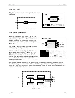
3.2.76 ROUT_ - Relay Outputs
ROUT_
function blocks provide SPDT contacts activated
by function block input C. The relay will turn on when the
block input is high (1) and will turn off when low (0).
Two relay outputs are available on the Expander Board.
Terminal Connections are listed in Section 7.4 Electrical
Installation.
ON
Input
RETENTIVE ON TIMER
L Y
D
e
L
a
Y
TIME
minutes
(S)
................ Real (0.0)
OD
O
utput
D
RETENTIVE
ROT_
ESN = 000
ON
E S N
E
xec.
S
eq.
N
o.
(H)
................. 001 to 250
E
M
I
N
T
U
P
N
I
INPUT EN
(H)
........
loop tag.block tag.output
(
null
)
D
T
U
T
P
L
S
P
ower
U
p
LAST
(S)
.................. NO/YES (YES)
A
ET
E
lapsed
T
ime
ON TIMER
EN
able Input
EN
ND
Output
N
ot
D
T
U
P
N
I
N
O
E
INPUT ON
(H)
........
loop tag.block tag.output
(
null
)
RT
R
emaining
T
ime
ROUT_no
ROUT_c
RELAY OUTPUT #_
RELAY OUTPUT
ROUT_
O
A
C
T I
N
ACTION
(H)
.......................... DIR/REV
DIR
SPDT Relay
INPUT C
(H)
.......
loop tag.block tag.output (null)
I N
P
U T
C
ROUT_nc
C
oil
C
BLOCK DIAGRAM
no
nc
C
c
D/A
BLOCK DIAGRAM
D
e
L
a
Y
TIME
O
utput D
ENable Input
EN
D
ON
ON Input
ET
O
utput ND
ND
.
.
RT
Summary of Contents for 353
Page 12: ...Contents UM353 1B x April 2012 ...
Page 22: ...Introduction UM353 1B April 2012 1 10 ...
Page 30: ...Configuration Overview UM353 1B April 2012 2 8 ...
Page 122: ...Function Blocks UM353 1B April 2012 3 92 ...
Page 168: ...Data Mapping UM353 1B April 2012 6 28 ...
Page 204: ...Controller and System Test UM353 1B April 2012 9 8 ...
Page 222: ...Calibration UM353 1B April 2012 11 4 ...
Page 226: ...Circuit Description UM353 1B April 2012 12 4 ...
Page 238: ...Model Designation and Specifications UM353 1B April 2012 13 12 EC Declaration of Conformity ...
Page 240: ...Model Designation and Specifications UM353 1B April 2012 13 14 ...
Page 244: ...Abbreviations And Acronyms UM353 1B 14 4 April 2012 ...

