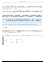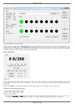
4.6.3. Controller status
Controller tracks its own status and can transfer it in the status structure of the
GETS
command. Controller status contains information
about performed movement, its result, state of power supply, state of encoder, state of motor windings, digital input-output states,
numeric information about position and powering voltage and currents and also error flags.
Movement status
MoveSts contains:
Movement flag which is set when controller changes motor position.
"Target speed reached" flag which is set if current speed is equal to the speed controller should be moving with.
Backlash compensation flag, which is set during backlash compensation in the final stage of the movement (see
MvCmdSts contains information about the command being executed. All motor movements are initiated by movement commands to
the MOVE target position, MOVR shift relative to the last target position, RIGT movement to the right, LEFT movement to the left,
smooth stop SSTP or fast stop STOP, HOME home position calibration and LOFT forced backlash compensation. Control by buttons,
joystick, sync in pulses, etc. is also performed by these commands. For example, joystick calls right and left movement commands
during deflection or smooth stop command in central position (see
). Current movement command or last command
and command status (running/completed) are located in MvCmdSts variable. If the command is completed then another bit shows its
result (successful or not). Unsuccessfully completed command means controller could not reach desired position or backlash
compensation could not be performed. The reason for this can be a sudden stop due to limit switches or Alarm state. Initial state of
this field contains unknown command and successful completion status.
Motor power supply status
PWRSts contains information about supply voltage. Windings' status can be:
Disabled (in this case no voltage is applied).
Powered by reduced current relative to nominal current (for example if winding current reduction option is used).
Powered by nominal current.
Powered by an voltage insufficient to reach nominal current in the windings.
Last status frequently appears with high rotation speeds, because for higher step switching speed one needs higher voltage to ensure
current rise in motor winding inductance. Insufficient voltage does not mean the motor won't move, it will merely emit excess noise
and its torque will drop (see
).
Encoder status
EncSts contains information about connected encoder if feedback is disabled (for example for stepper motors). Encoder state can be
one of the following:
Not connected
Unknown state, when there is not enough data to define encoder state.
Connected and working.
Connected and reversed, in this case it is necessary to enable reverse in encoder settings.
Connected and defective.
The last state is realized when switch signals come to encoder inputs but they don't correspond to the motor rotor movement. State
change happens after sufficient statistical data is collected. That's why detection doesn't happen immediately. It is also impossible to
define encoder status without movement (see
).
Motor windings status
WindSts contains information about windings state. State of each of the two windings is shown separately. They can be:
Disconnected from controller
Connected
Short-circuited
In an unknown state.
A state with very small resistance and inductance is considered to be a short-circuit. A state with very high load resistance is
considered to be disconnected.
Position status.
All data about stage position and speed is reflected in status structure. Fields of primary position (CurPosition, uStep), secondary
position (EncPosition), speeds (CurSpeed, uCurSpeed) are used for this. Primary position is counted in steps and microsteps of stepper
motor if control without feedback is used. In case of leading encoder mode
encoder counts are stored in CurPosition and uStep contains 0. Secondary position contains encoder coordinate if no feedback is used
for stepper motor, contains steps if a stepper motor with encoder feedback is used and contains 0 if DC motor is used. Speed is always
displayed for the primary position and is measured in the same units as the current set speed.
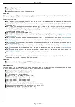
Controller power supply status and temperature.
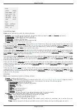
Status structure reflects:
Power current (in mA)
Page 107 / 345
Page 107 / 345
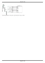
Summary of Contents for 8SMC5-USB
Page 30: ...Linux Page 30 345 Page 30 345 ...
Page 83: ...Connection of magnetic brake to one axis or two axis systems Page 83 345 Page 83 345 ...
Page 87: ...Scheme of buttons connection to the HDB 26 connector Page 87 345 Page 87 345 ...
Page 99: ...Page 99 345 Page 99 345 ...
Page 167: ...Vertical load capacity the maximum vertical load on the stage Page 167 345 Page 167 345 ...
Page 186: ...Click Next Click Continue anyway Page 186 345 Page 186 345 ...
Page 188: ...Page 188 345 Page 188 345 ...
Page 190: ...Page 190 345 Page 190 345 ...
Page 193: ...Page 193 345 Page 193 345 ...
Page 201: ...Select the XILab application in the Programs block Start it Page 201 345 Page 201 345 ...
Page 274: ...7 Files 1 Configuration files 2 Software Page 274 345 Page 274 345 ...
Page 331: ...Motorized Iris Diaphragms 8MID98 Motorized Iris Diaphragm Page 331 345 Page 331 345 ...
Page 338: ...8 Related products 1 Ethernet adapter Page 338 345 Page 338 345 ...
Page 339: ...8 1 Control via Ethernet 1 Overview 2 Administration Page 339 345 Page 339 345 ...

