4.
Open the dialog window "Properties" by a double click to the
Count
submodule of
the CPU.
5.
As soon as an operating mode to the corresponding channel is selected, a dialog
window for this operating mode is created and displayed and filled with default
parameters.
6.
Execute the wished parameterization.
7.
Save the project with
‘Station
è
Save and compile’
.
8.
Transfer the project to the CPU.
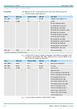
The SFB COUNT (SFB 47) should cyclically be called (e.g. OB 1) for controlling the
counter functions. The SFB is to be called with the corresponding instance DB. Here the
parameters of the SFB are stored. Among others the SFB 47 contains a request inter-
face. Hereby you get read and write access to the registers of the appropriate counter. So
that a new job may be executed, the previous job must have be finished with JOB_DONE
= TRUE. Per channel you may call the SFB in each case with the same instance DB,
since the data necessary for the internal operational are stored here. Writing accesses to
outputs of the instance DB is not permissible.
You must not call an SFB you have configured in your program in another
program section under another priority class, because the SFB must not
interrupt itself. Example: It is not allowed to call the same SFB both in OB
1 and in the interrupt OB.
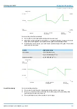
The counter is controlled by the internal gate (i gate). The i gate is the result of logic oper-
ation of hardware gate (HW gate) and software gate (SW gate), where the HW gate eval-
uation may be deactivated by the parameterization.
HW gate:
open (activate):
Edge 0-1 at hardware gate
x
input of the
module
close (deactivate):
Edge 1-0 at hardware gate
x
input of the
module
SW gate:
open (activate):
In application program by setting
SW_GATE of the SFB 47
close (deactivate):
In application program by resetting
SW_GATE of the SFB 47
The counter values may be read by the output parameter COUNTVAL of the SFB 47.
There is also the possibility for direct access to the counter values by means of the input
address of the
Count
submodule.
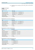
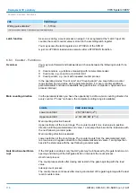
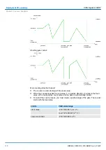
There are the following possibilities for connection to the technological functions:
n
24V incremental encoder, equipped with two tracks with 90° phase offset
n
24V pulse generator with direction signal
n
24V proximity switch (e.g. BERO or light barrier)
Controlling the counter
functions
Controlling the counter
Read counter
Counter inputs (Connec-
tions)
VIPA System 300S
+
Deployment I/O periphery
Counter > Counter - Fast introduction
HB140 | CPU-SC | 313-5BF23 | en | 19-01
108


