104
Operation Theory
4.1.12 Manual Pulser Mode (PCI-8164 Only)
For manual operation of a device, you may use a manual pulse
such as a rotary encoder. The PCI-8164 can receive input signals
from a pulser and output its corresponding pulses from the OUT
and DIR pins, thereby allowing a simplified external circuit.
This mode is effective when the
_8164_pulser_vmove()
,
_8164_pulser_pmove()
, or
_8164_pulser_home_move()
command has been called. To terminate the command use the
_8164_sd_stop()
or_8164_emg_stop()
command.
The PCI-8164 receives positive and negative pulses (CW/CCW)
or 90-degree phase difference signals (AB phase) from the pulser
at the PA and PB pins. To set the input signal modes of the pulser,
use the
_8164_set_pulser_iptmode()
function. The 90-
degree phase difference in signals can be set by a multiplication of
1, 2, or 4. If the AB phase input mode is selected, PA and PB sig-
nals should have a 90-degree phase shift, and the position
counter increases when the PA signal is leading the PB signal by
90 degrees.
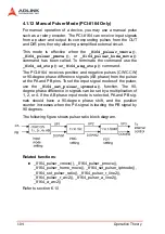
The following figure shows pulser ratio block diagram.
Related functions
:
X
_8164_pulser_vmove(), _8164_pulser_pmove(),
_8164_pulser_home_move(), _8164_set_pulser_iptmode(),
_8164_set_pulser_ratio(), _8164_pulser_r_line2(),
_8164_pulser_r_arc2(), _8164_pulser_a_line2(),
_8164_a_arc2()
Refer to section 6.10
Summary of Contents for MPC-8164
Page 4: ......
Page 12: ......
Page 14: ...2 Introduction Figure 1 1 PCI 8164 block diagram ...
Page 50: ...38 Installation ...
Page 70: ...58 Signal Connections ...
Page 74: ...62 Signal Connections 3 17 1 Isolated input channels 3 17 2 Isolated output channels ...
Page 75: ...Signal Connections 63 3 17 3 Example of input connection ...
Page 76: ...64 Signal Connections 3 17 4 Example of output connections ...
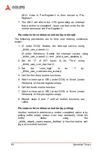
Page 109: ...Operation Theory 97 ...
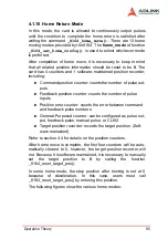
Page 110: ...98 Operation Theory ...
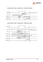
Page 111: ...Operation Theory 99 ...
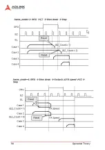
Page 112: ...100 Operation Theory ...
Page 113: ...Operation Theory 101 ...
Page 148: ...136 Operation Theory Users can use this function to check if auto trigger is running Results ...
Page 280: ...268 Connection Example Figure 7 2 Connection of PCI 8164 with Panasonic Driver ...
Page 287: ...Connection Example 275 7 3 3 Mechanical Dimensions ...
Page 297: ...Connection Example 285 7 5 2 Mechanical Dimensions ...
Page 300: ...288 Connection Example 7 6 Wiring with DIN 814M J3A ...
Page 304: ...292 Connection Example 7 7 Wiring with DIN 814Y ...
Page 308: ...296 ...

