19
: P
an
el D
es
ig
ne
r •
10
6
© 2017 Telos Alliance - Rev 1.2
To use this panel within PathfinderPC_Core Mini, edit the configuration file and be sure the server IP addresses are
defined, and enter the PanelName to open in the configuration file. See the section on PathfinderPC_Core Mini for
details. Launching PathfinderPC_Core Mini will run this panel as its own application.
If you close and reopen the panel designer, you can use the File menu to open and edit the Panel if you want to
change it later. Once you re-save the changes you must close and open the panel again within PathfinderPC_Core
Client to get the changes to display. In PathfinderPC_Core Mini, just close and re-launch the application to view
your changes. You can also create additional panels and save them to the folder, and they will be available to these
applications.
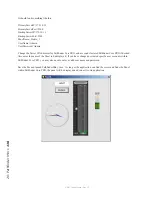
Remember that the MapRouter/Source/Destination is only one thing you can do with the panels. You could also
leave these fields blank and use Logic Flows to determine the button functions. The section on latching buttons in
the Logic Flows section of this document is a good example. In addition the detailed property descriptions below
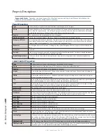
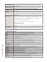
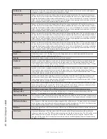
will provide more insight on the wide variety of functions these controls can perform.
To continue with our example, open the Panel you were just designing in Panel Designer again. One of the other
powerful features of these panels is that once created, their button functions can be mapped to actual hardware
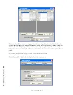
controls as well using either GPIO circuits or Axia Element User Panel buttons. To accomplish this, select the
button you wish to map to a hardware control, and then find the HWMapType property and select the Button, Label,
or GPIO button option. You then must select a different property for the change to update. Essentially you must
leave the property for the change to get written into the panel definition. This is true of most of the properties. The
Button option means that this button will get mapped to an Axia User Panel button. The Label property means that
this button will be mapped to the LCD display of an Axia User Panel. The GPIO Button option means that it will
map to a GPIO Circuit. You will notice that once you make your selection and then leave the selection field the
options in the HWMap section will change depending on whether a GPIO option or User Panel option was selected.
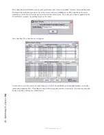
Next under HWMapHostIP enter the IP address of the Element CPU or GPIO box that hosts the hardware device to
be used. The HWMapHostPort will have already been selected when the HWMapType was selected and should not
be casually changed. The HWMapInternalName Property is also automatically defined and matches the software
PanelName.ControlName to which you are mapping. The HWMapAxiaSysName is automatically defined by the
last two properties on the list, and cannot be manually set. If you have selected a GPIO type map then these last
two properties will be GPIO Port and GPIO Circuit. Enter the number of the port on the device defined by the
HWMapHostIP, and the GPI/GPO pin to use.
If the HWMapType is a UserPanel Button or Label (LCD Display), then these properties will be UserPanelModule
and UserPanelButton. The module number is related to the dip switch setting on the bottom of the module in the
console. However, there is a much simpler method for obtaining the module number if you don’t know it. Open a
command prompt and type:
telnet ipaddress 4010
example:
Telnet 172.16.1.3 4010

