Appendix
A - 3
A.2.1
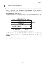
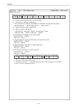
Modbus message configuration
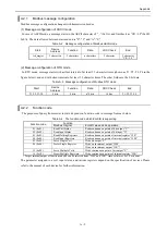
Modbus message configuration changes with transmission modes.
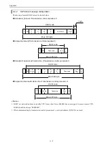
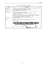
(1) Message configuration of ASCII mode
In case of ASCII mode, a message starts in the ASCII character of “ : ”(0x3A), and finishes it as ”CR / LF”(0x0D,
0x0A). The data allowed between start and end is "0"-" 9" and "A"-"F."
Table A.2 Message configuration of Modbus ASCII mode
Start
Device
Address
Function
Data
LRC Check
End
1 character
“ : ”
2 characters
2 characters
n characters
2 character
2 character
“ CR / LF ”
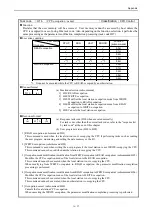
(2) Message configuration of RTU mode
In RTU mode, message starts with a silent interval of at least 3.5 character times (shown as T1–T2–T3–T4 in the
figure below), and end with silent interval of at least 3.5 character times. The other fields are the 8-bit data.
Table A.3 Message configuration of Modbus RTU mode
Start
Device
Address
Function
Data
CRC Check
End
T1-T2-T3-T4
8 bits
8 bits
n*8 bits
16 bits
T1-T2-T3-T4
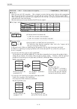
A.2.2
Function code
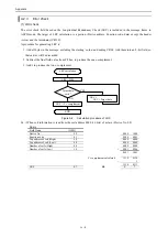
The purposes of query from master to slave depends on function code in message frame as below.
Table A.4 The function code which EH-SIO is supporting
Function code
Function
Modbus Original
EH-SIO slave mode operation
01 (0x01)
Read Coil Status
Read continuous n points of bit output “Y”
02 (0x02)
Read Input Status
Read continuous n points of bit input “X”
03 (0x03)
Read Holding Registers
Read continuous n points of internal register “WR”
04 (0x04)
Read Input Registers
Read continuous n points of internal register “WM”
05 (0x05)
Force Single Coil
Write bit output “Y”
06 (0x06)
Preset Single Register
Write word internal output “WM”
Write word internal output “WR” *
15 (0x0F)
Force Multiple Coils
Write continuous n point of bit output “Y”
16 (0x10)
Preset Multiple Registers
Write continuous n points of internal register “WR”
* Target internal output of function code 06 can be selected from “WM” and “WR” since software ver. 3.0 or newer.
The parameter assigned to a coil, input status, and various registers depend on the specification of devices. Please
refer to the manual of each device for further information.
Summary of Contents for EH-150 Series
Page 2: ......
Page 10: ...M E M O ...
Page 30: ...Chapter 4 Installation 4 10 M E M O ...
Page 156: ...Chapter 7 System setup 7 12 M E M O ...
Page 164: ...Chapter 8 Daily and Periodic Inspection 8 8 M E M O ...

