Chapter6 Communication Mode
6 - 26
F
re
e
P
ro
to
col
[EHV-CPU]
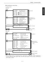
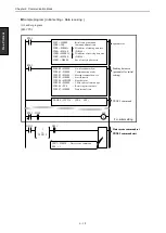
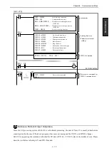
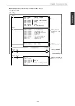
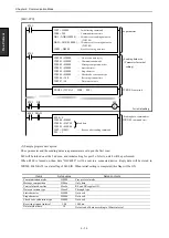
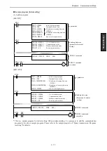
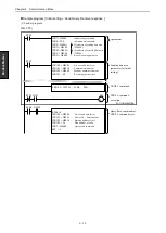
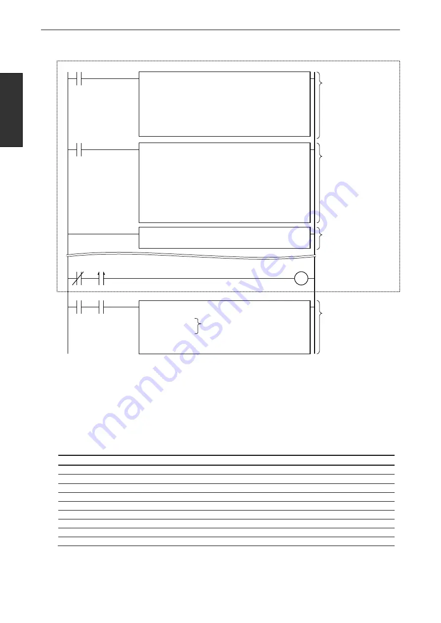
(2) Sample program description
The s parameter and the sending data area parameter are set upon the first scan.
M0 will be turned on at the 2nd scan, and initial setting for port 2 of slot A, unit 4 will be performed.
When R100 is turned on, then data “H4C4F4E” will be sent to a connected device. Reply data will be stored in
WR200. Bit X4A29 is a status flag of EH-SIO. When initial setting is completed, this flag will be ON.
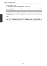
Items
Setup value
Setup contents
Communication mode
H0000
Free protocol mode
Message composition
H00xx
Only data
Control of modem line
Hxx0x
RS and ER regular ON
Data conversion type
Hxxx0
Through type
Start character
H0000
Not used
Stop character
H0000
Not used
Check code calculation type
H0000
Not used
Receiving timeout interval
100
1000 ms
Data interval time
10
Detect end of data according to 100ms interval
TRNS 9 ( WY4A5 , WR0 , M0 )
WR7 = H0000
…
Initial setting command
WR8 = 200
…
Command timeout time
DR9 =ADR(WR100)
…
I/O address of sending data area
( WR100 )
DRB = ADR(WR200)
…
I/O address of receiving data area
( WR200 )
WRD = H0400
…
Size of receiving data area
R7E3
s parameter
TRNS 9
command
WR100 = H000E
…
No. of send data (byte)
WR101 = H0000
…
Communication mode
WR102 = H0000
…
Message composition, other
WR103 = H0000
…
Start character
WR104 = H0000
…
Stop character
WR105 = H0000
…
Check code convention type
WR106 = 100
…
Receiving timeout time
WR107 = 10
…
Data interval time
R7E3
Sending data area
(Parameter for initial
setting)
R7E3
M0
S
DIF
For initial setting
R100 = 0
WR100 = H0003
WR101 = H4C4F
WR102 = H4E00
WR7 = H0021
…
Receive after sending command
M0 = 1
Sending data, command set
TRNS 9
command start
R100 X4A29
Send data
Summary of Contents for EH-150 Series
Page 2: ......
Page 10: ...M E M O ...
Page 30: ...Chapter 4 Installation 4 10 M E M O ...
Page 156: ...Chapter 7 System setup 7 12 M E M O ...
Page 164: ...Chapter 8 Daily and Periodic Inspection 8 8 M E M O ...

