Appendix
A - 4
A.2.3
Error check
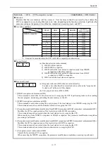
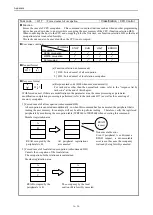
(1) LRC check
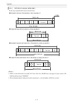
The error check field based on the Longitudinal Redundancy Check (LRC) is included in the message frame in
ASCII mode. The target of LRC calculation is a portion (Device address, Function code, data) except the header
(colon) and the terminator (CR/LF).
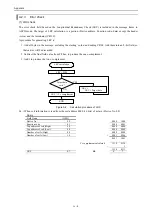
A procedure for generating LRC is:
1. Add all bytes in the message, excluding the starting ‘colon’ and ending CRLF. Add them into an 8–bit field, so
that carries will be discarded.
2. Subtract the final field value from FF hex, to produce the ones–complement.
3. Add 1 to produce the twos–complement.
LRC calculation
Target data
exist ?
YES
NO
LRC = H00
LRC =
LRC + Target data
LRC
2’s complement
END
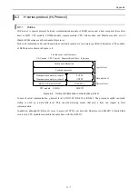
Figure A.2 Calculation procedure of LRC
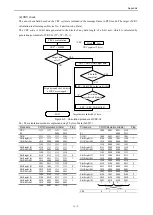
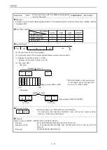
Ex. ) When coil information is read from the coil address 0000 (16 bits) of a slave (Device No. 08)
Query
Field Name
(HEX)
Device No.
08
0000
1000
Function code
01
0000
0001
Top address of coil (High)
00
0000
0000
Top address of coil (Low)
00
0000
0000
Number of coils (High)
00
0000
0000
Number of coils (Low)
10
+
0001
0000
0001
1001
2’s complement calculated
1110
0110
+
1
1110
0111
LRC
E7
E
7
Summary of Contents for EH-150 Series
Page 2: ......
Page 10: ...M E M O ...
Page 30: ...Chapter 4 Installation 4 10 M E M O ...
Page 156: ...Chapter 7 System setup 7 12 M E M O ...
Page 164: ...Chapter 8 Daily and Periodic Inspection 8 8 M E M O ...

