XC2200 Derivatives
System Units (Vol. 1 of 2)
System Control Unit (SCU)
User’s Manual
6-42
V2.1, 2008-08
SCU, V1.13
6.1.7.7
External Clock Control Register
This register control the setting of external clock for pin 2.8 and 7.1.
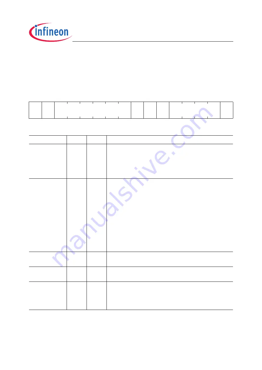
EXTCON
External Clock Control Register SFR (FF5E
H
/AF
H
)
Reset Value: 0000
H
15
14
13
12
11
10
9
8
7
6
5
4
3
2
1
0
FO
EN
FO
SS
FORV
0
FO
TL
0
SEL
EN
rw
rw
rw
r
rh
r
rw
rw
Field
Bits
Type
Description
EN
0
rw
External Clock Enable
0
B
No external clock signal is provided. The signal
is tied to zero.
1
B
The configured external clock signal is
provided as alternate output signal
SEL
[4:1]
rw
External Clock Select
Selects the clock signal to be routed to the EXTCLK
pin:
0000
B
System clock
f
SYS
0001
B
Programmable clock signal
f
OUT
0010
B
PLL output clock
f
PLL
0011
B
Oscillator clock
f
OSC
0100
B
Wake-up clock
f
WU
0101
B
Direct Input clock
f
CLKIN1
1000
B
RTC count clock
f
RTC
All other combination are reserved, do not use.
FOTL
6
rh
Frequency Output Toggle Latch
Toggled upon each underflow of FOCNT.
FORV
[13:8]
rw
Frequency Output Reload Value
Copied to FOCNT upon each underflow of FOCNT.
FOSS
14
rw
Frequency Output Signal Select
0
B
Output of the toggle latch
1
B
Output of the reload counter: duty cycle
depends on FORV


