96
VCCX2 Controller Technical Guide
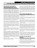
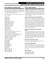
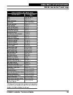
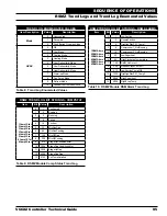
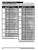
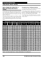
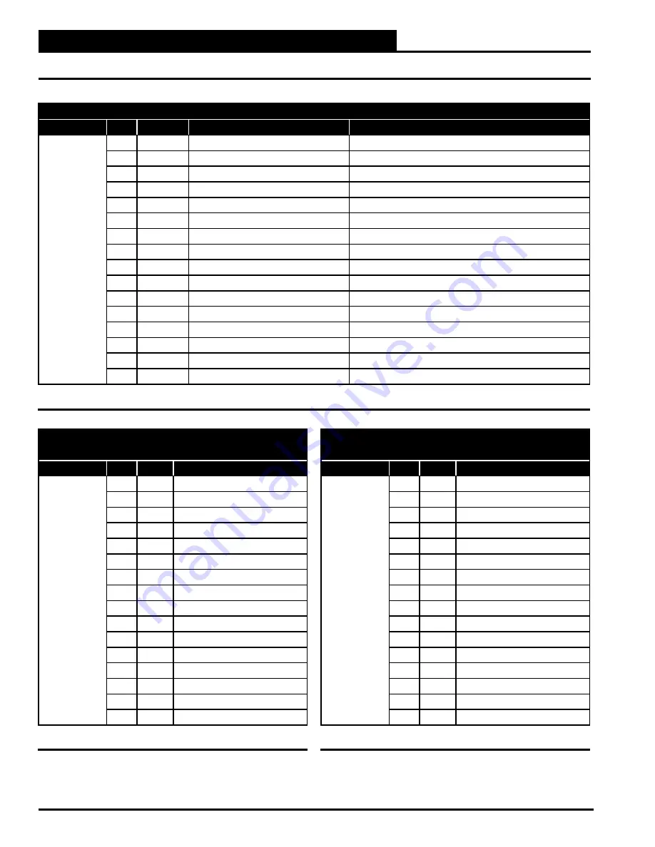
RSMZ TREND LOG BIT STRINGS - VFD STATUS
Item
Bit
Value
VFD Status (Bit = 0)
VFD Status (Bit = 1)
1VFDStat
2VFDStat
3VFDStat
4VFDStat
5VFDStat
6VFDStat
0
1
0 = Control Not Ready
1 = Control Ready
1
2
0 = Drive Not Ready
1= Drive Ready
2
4
0 = Coasting
1 = Enable
3
8
0 = No Error
1 = Trip
4
16
0 = No Error
1 = Error (no trip)
5
32
Reserved
6
64
0 = No Error
1 = TripLock (must cycle power)
7
128
0 = No Warning
1 = Warning
8
256
0 = Speed Not Equal Reference
1 = Speed Equal Reference
9
512
0 = Local Operation
1 = Bus Control
10
1024
0 = Out of Frequency Limit
1 = Frequency Limit Okay
11
2048
0 = No Operation
1 = In Operation
12
4096
0 = Drive Okay
1 = Stopped, Auto Start
13
8192
0 = Voltage Okay
1 = Voltage Exceeded
14
16384
0 = Torque Okay
1 = Torque Exceeded
15
32768
0 = Timer Okay
1 = Timer Exceeded
Table 11: RSMZ Module VFD Status Trend Log
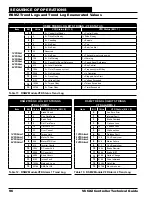
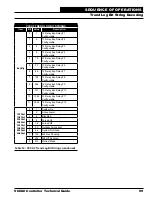
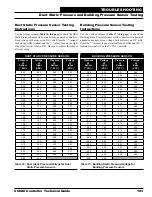
RSMZ TREND LOG BIT STRINGS
VFD ALARMS 1
Item
Bit
Value
VFD Status (Bit = 0)
1VFDAlrm1
2VFDAlrm1
4VFDAlrm1
5VFDAlrm1
0
1
Brake Check
1
2
Pwr. Card Temp
2
4
Earth Fault
3
8
Ctrl. Card Temp
4
16
Ctrl. Word TO
5
32
Over Current
6
64
Torque Limit
7
128
Motor Th Over
8
256
Motor ETR Over
9
512
Inverter Overld.
10
1024
DC under Volt
11
2048
DC over Volt
12
4096
Short Circuit
13
8192
Inrush Fault
14
16384
Mains ph. Loss
15
32768
AMA Not OK
Table 12: RSMZ Module VFD Alarm 1 Trend Log
RSMZ TREND LOG BIT STRINGS
VFD ALARMS 2
Item
Bit
Value
VFD Status (Bit = 0)
1VFDAlrm2
2VFDAlrm2
4VFDAlrm2
5VFDAlrm2
0
1
Live Zero Error
1
2
Internal Fault
2
4
Brake Overload
3
8
U phase Loss
4
16
V phase Loss
5
32
W phaseLoss
6
64
Fieldbus Fault
7
128
24 V Supply Low
8
256
Mains Failure
9
512
1.8V Supply Low
10
1024
Brake Resistor
11
2048
Brake IGBT
12
4096
Option Change
13
8192
Drive Initialized
14
16384
Safe Stop
15
32768
Mech brake low
Table 13: RSMZ Module VFD Alarm 2 Trend Log
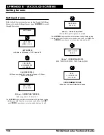
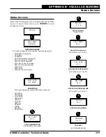
SEQUENCE OF OPERATIONS
RSMZ Trend Logs and Trend Log Enumerated Values


