Trace Configuration
QT
RACE
-
U
SER
M
ANUAL
© 2018 PDQLogic Ltd.
QTrace User Manual Rev 1.01
Page 34
6.
Trace Configuration
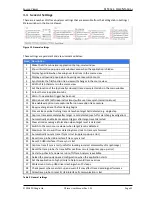
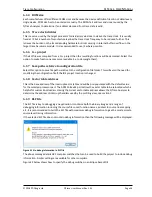
Before tracing can begin, a trace configuration needs to be created. This is done by selecting the Menu
option
File
New Configuration...
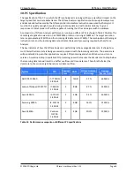
or by clicking the highlighted toolbar button:
Figure 38 Selecting a new trace configuration
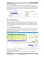
This will prompt for the name and location to save a new
.tcf
configuration file. The location is typically
the top level project folder. Once the file name and location are specified, the trace configuration dialog
will be displayed.
The following sections describe the configuration process in detail.
6.1
Trace configuration dialog
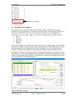
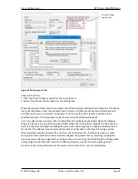
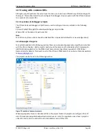
Figure 39 shows the ‘new trace configuration’ dialog and a summary of its fields:
Figure 39 Trace configuration dialog
1,2
Drop down lists of supported device
manufacturers and parts
3
Summary specification of selected device
4,5
Start address and size of program ROM
6
Trace clock divider is usually fixed at SYS-
CLK/2 but certain devices offer other options
7
Tick if project is a C++ project rather than C
8
Tick to save source file paths relative to the
configuration file
9
Base address of the interrupt vector table
10
Path of ELF / AXF file loaded into the
target by the debugger
11
Paths where source files used to build ELF
file can be located
12
Source files that cannot be located on the
filing system e.g. library source files
13
Memory range(s) of additional program
space e.g. boot ROM
14
Specifies if target trace is configured by
the debugger or by the firmware application
15
Base address
of RAM used by debugger
trace configuration script
16
Path of the debugger script file used to
configure target trace
17
Voltage range of the target trace pins


