KS57C2308/P2308/C2316/P2316
I/O PORTS
10-3
PORT MODE FLAGS (PM FLAGS)
Port mode flags (PM) are used to configure I/O ports to input or output mode by setting or clearing the
corresponding I/O buffer.
For convenient program reference, PM flags are organized into two groups — PMG1 and PMG2 as shown in
Table 10-3. They are addressable by 8-bit write instructions only.
When a PM flag is "0", the port is set to input mode; when it is "1", the port is enabled for output.
RESET
clears all
port mode flags to logical zero, automatically configuring the corresponding I/O ports to input mode.
Table 10-3. Port Mode Group Flags
PM Group ID
Address
Bit 3/7
Bit 2/6
Bit 1/5
Bit 0/4
PMG1
FE8H
PM3.3
PM3.2
PM3.1
PM3.0
FE9H
PM6.3
PM6.2
PM6.1
PM6.0
PMG2
FECH
“0”
PM2
“0”
“0”
FEDH
PM7
“0”
PM5
PM4
+
+
PROGRAMMING TIP — Configuring I/O Ports to Input or Output
Configure ports 3 and 6 as an output port:
BITS
EMB
SMB
15
LD
EA,#0FFH
LD
PMG1,EA
; P3 and P6
←
Output
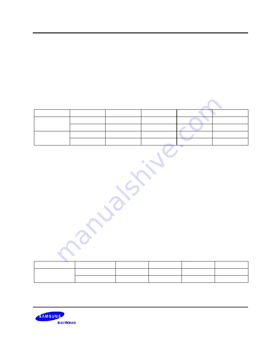
PULL-UP RESISTOR MODE REGISTER (PUMOD)
The pull-up resistor mode registers (PUMOD1 and PUMOD2) are used to assign internal pull-up resistors by
software to specific ports. When a configurable I/O port pin is used as an output pin, its assigned pull-up resistor
is automatically disabled, even though the pin's pull-up is enabled by a corresponding PUMOD bit setting.
PUMOD1 is addressable by 8-bit write instructions only, and PUMOD2 by 4-bit write instruction only.
RESET
clears PUMOD register values to logic zero, automatically disconnecting all software-assignable port pull-up
resistors.
Table 10-4. Pull-Up Resistor Mode Register (PUMOD) Organization
PUMOD ID
Address
Bit 3/7
Bit 2/6
Bit 1/5
Bit 0/4
PUMOD
FDCH
PUR3
PUR2
PUR1
PUR0
FDDH
PUR7
PUR6
PUR5
PUR4
NOTE:
When bit = "1", a pull-up resistor is assigned to the corresponding I/O port: PUR3 for port 3, PUR2 for port 2,
and so on.
Summary of Contents for KS57C2308
Page 30: ...ADDRESS SPACES KS57C2308 P2308 C2316 P2316 2 22 NOTES ...
Page 168: ...SAM47 INSTRUCTION SET KS57C2308 P2308 C2316 P2316 5 94 NOTES ...
Page 170: ......
Page 206: ...POWER DOWN KS57C2308 P2308 C2316 P2316 8 8 NOTES ...
Page 210: ...RESET KS57C2308 P2308 C2316 P2316 9 4 NOTES ...
Page 222: ...I O PORTS KS57C2308 P2308 C2316 P2316 10 12 NOTES ...
Page 272: ...LCD CONTROLLER DRIVER KS57C2308 P2308 C2316 P2316 12 24 NOTES ...
Page 280: ...SERIAL I O INTERFACE KS57C2308 P2308 C2316 P2316 13 8 NOTES ...
Page 294: ...MECHANICAL DATA KS57C2308 P2308 C2316 P2316 15 2 NOTES ...
Page 310: ...KS57P2308 P2316 OTP KS57C2308 P2308 C2316 P2316 16 16 NOTES ...
Page 318: ......
Page 320: ......
Page 322: ......
Page 325: ......
Page 327: ......

