TRIO MPC-145 SERIES MICROMANIPULATOR SYSTEM OPERATION MANUAL – REV. 2.62C (20191001) (FW V2.62)
30
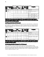
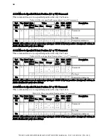
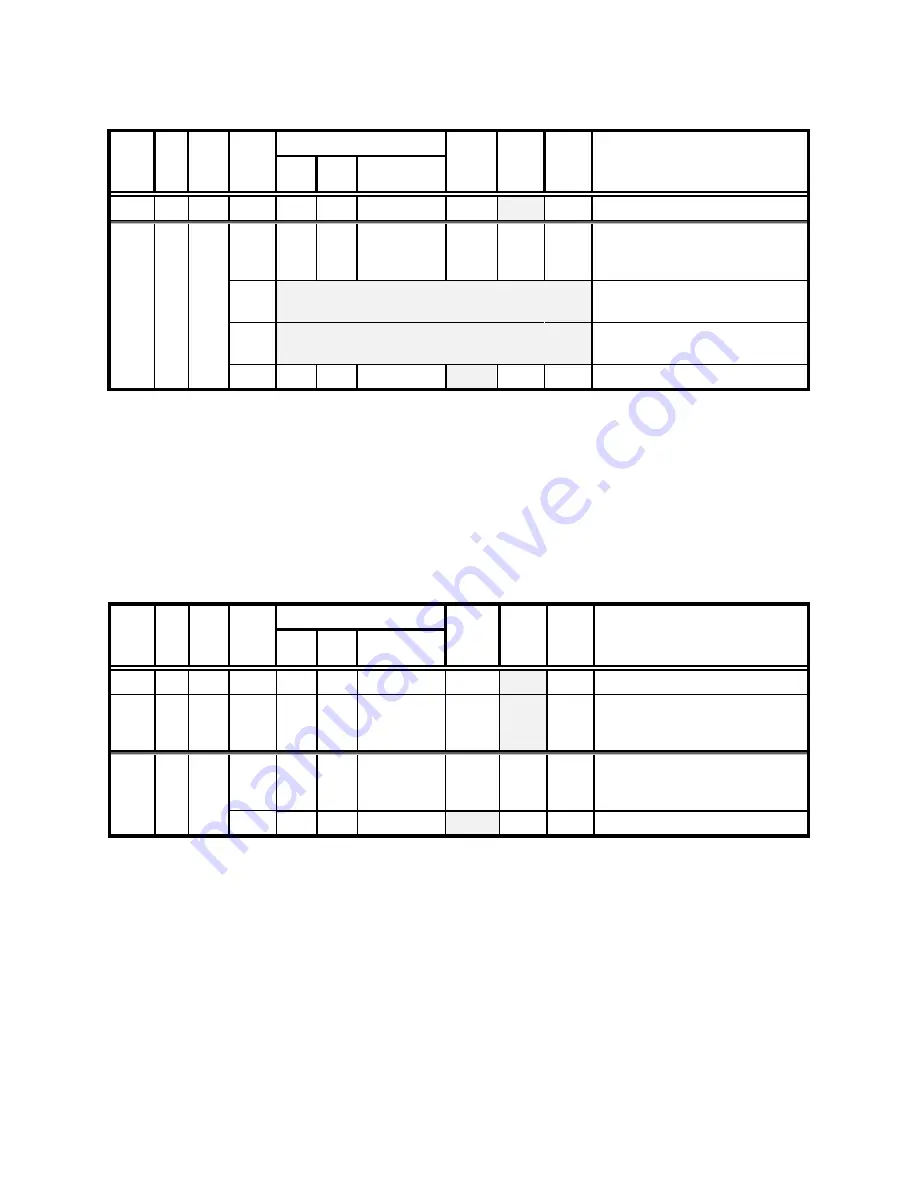
Table 4-4. Get Active Device & Firmware Version (‘K’) command.
Tx/-
Delay
/-Rx
Ver. Total
Bytes
Byte
Offset
(Len.)
Value
Alt-
key-
pad #
Ctrl-
char
ASCII
def./-
char.
Description
Dec. Hex.
Binary
Tx All
1
0
75 4B 0100 1011 0075
K
Command
Rx All
4
0
1
-
2
01
-
02
0000 0001
–
0000 0010
^A
-
^B
<SOH>
-
<STX>
Currently-active device (1 – 2
(A – B)).
1
Major version number (e.g., if
ver. = 2.62, then byte = 2)
2
Minor version number (e.g., if
ver. = 2.62, then byte = 62)
3
13 0D 0000 1101
^M <CR>
Completion indicator
NOTE: The device number returned by the ‘K’ command indicates the active device for
external commands only; it is completely independent of the manual A and B switch on the
front of the MPC-100 ROE/controller.
4.6.2
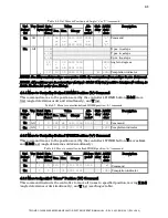
Change Active Device (‘I’) Command
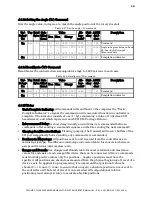
This command is used to change the currently-active device attached to the controller. One
byte follows the command, consisting of a value of 1 (for Device A) or 2 (for Device B). Two
bytes are returned: The first contains the device specified as confirmation, followed by the
completion indicator.
Table 4-5. Change active device (‘I’) command.
Tx/-
Delay
/-Rx
Ver. Total
Bytes
Byte
Offset
(Len.)
Value
Alt-
key-
pad #
Ctrl-
char
ASCII
def./-
char.
Description
Dec. Hex.
Binary
Tx All
2
0
73 49 0100 1001 0073
I
Command
1 1-2 01
-
02
0000 0001
-
0000 0010
0001
-
0002
^A
-
^B
<SOH>
-
<STX>
Manipulator to be made active
(by value: 1(for A) or 2 (for B)
Rx All
2
0 1-2 01
-
02
0000 0001
-
0000 0010
^A
-
^B
<SOH>
-
<STX>
Manipulator value specified
1
13 0D 0000 1101
^M <CR>
Completion indicator
NOTE: The device number specified with the ‘I’ command is the active device for external
commands only; it is completely independent of the manual A and B switch on the front of
the MPC-100 ROE/controller.
4.6.3
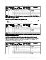
Get Current Position and Angle (‘c’ or ‘C’) Command
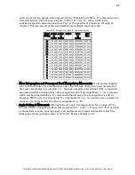
This command is used to obtain the current position (X, Y, & Z coordinates) of the
manipulator or stage and the current angle setting. The command sequence consists of one
byte as shown in the following table. The data received consists of fourteen bytes containing
X, Y, & Z position (32-bit) values in microsteps (4 bytes each), the angle in degrees (1 byte),
and the completion indicator (1 byte).

